Table of Contents
Advertisement
Quick Links
Download this manual
See also:
User Manual
Advertisement
Table of Contents

Related Manuals for Kramer VP-1608


Summary of Contents for Kramer VP-1608
- Page 1 Kramer Electronics, Ltd. USER MANUAL Model: VP-1608 16x8 RGBHV / Balanced Audio Matrix...
-
Page 3: Table Of Contents
Summary of how to Operate a Single Machine Your VP-1608 16x8 RGBHV / Balanced Audio Matrix Displaying Unit Characteristics Connecting a VP-1608 16x8 RGBHV / Balanced Audio Matrix Connecting the Balanced/Unbalanced Stereo Audio Input/Output Controlling via RS-232 (for example, using a PC) - Page 4 Figure 21: Atmel – Flip Window (Operation Completed) Tables Table 1: Front Panel VP-1608 16x8 RGBHV / Balanced Audio Matrix Features Table 2: Rear Panel VP-1608 16x8 RGBHV / Balanced Audio Matrix Features Table 3: VP-1608 Underside (Flash Program Switches) Features...
-
Page 5: Introduction
The high performance VP-1608 16x8 RGBHV / Balanced Audio Matrix is a true matrix switcher, routing any input to any or all outputs simultaneously. The VP-1608 includes 16 input and eight output selector buttons, as well as: A bandwidth of 400MHz (Fully Loaded) for RGB signals... -
Page 6: Summary Of How To Operate A Single Machine
Kramer VP-1608 away from moisture, excessive sunlight and dust Summary of how to Operate a Single Machine By default, the VP-1608 is setup for use as a single machine. This means that it is a 16x8 RGBHV / Balanced Audio Matrix (in audio-follow-video mode), with all setups empty and each input connected to its corresponding output (for example, input 1 to output 1). -
Page 8: Table 1: Front Panel Vp-1608 16X8 Rgbhv / Balanced Audio Matrix Features
Your VP-1608 16x8 RGBHV / Balanced Audio Matrix Table 1: Front Panel VP-1608 16x8 RGBHV / Balanced Audio Matrix Features Feature Function 1 IR Receiver The red LED is illuminated when receiving signals from the Kramer Infra-red remote control transmitter... -
Page 9: Figure 3: Vp-1608 Underside Flash Program Switches
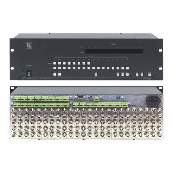
Your VP-1608 16x8 RGBHV / Balanced Audio Matrix Table 2: Rear Panel VP-1608 16x8 RGBHV / Balanced Audio Matrix Features Feature Function 1 AUDIO OUT Terminal Block Connectors Connect to the audio acceptors (from 1 to 8) 2 RS-232 DB 9F Connector... -
Page 10: Displaying Unit Characteristics
Your VP-1608 16x8 RGBHV / Balanced Audio Matrix 5.1 Displaying Unit Characteristics the VP-1608 unit, momentarily displays the Switching on and/or resetting following characteristics on the front panel (as Figure 4 illustrates): The number included in the product name (for example, 1608) -
Page 11: Connecting A Vp-1608 16X8 Rgbhv / Balanced Audio Matrix
Figure 5: Connecting the Video Sources and Acceptors to the Rear Panel 1 Note that you can connect up to 8 VP-1608 units to a PC or other RS-232 or RS-485 controller (see section 7) 2 Switch OFF the power on each device before connecting it to your VP-1608. After connecting your VP-1608, switch on its... -
Page 12: Connecting The Balanced/Unbalanced Stereo Audio Input/Output
Connecting a VP-1608 16x8 RGBHV / Balanced Audio Matrix 6.1 Connecting the Balanced/Unbalanced Stereo Audio Input/Output This section illustrates how to wire: A balanced input/output connection, see Figure 6 An unbalanced audio input, see Figure 7 An unbalanced audio output, see Figure 8... -
Page 13: Controlling Via Rs-232 (For Example, Using A Pc)
Figure 9: Connecting a PC without using a Null-modem Adapter 1 When connecting a single VP-1608 unit via RS-232, set the MACH. # dipswitches to Machine # 1, according to Table 4 2 Up to 50 feet of cabling may be used for the RS-232 connection... -
Page 14: Controlling Via Rs-485
“G” (Ground) PIN on one of the units (for example, on the RC-3000) 2. Set the MACH. # dipswitches on the VP-1608 unit to a Machine # between 2 and 16, according to Table 4. Do not set as Machine # 1 (the Master). -
Page 15: Setting The Machine # Dipswitches
VP-1608 unit is being controlled when several VP-1608 units are controlled by a PC or serial controller. Set the MACHINE # on a VP-1608 unit via DIPS 1, 2, and 3 (DIP 4 is for RS-485 termination), according to Table 4. -
Page 16: Setting The Delay Dipswitches
3 To connect a single VP-1608 unit to a PC or other RS-485 controller, see section 6.3 4 Switch OFF the power on each device before connecting it to your VP-1608. After connecting your VP-1608, switch on its power and then switch on the power on each device... -
Page 17: Figure 11: Control Configuration Via Rs-232 And Rs-485
Controlling 16x8 RGBHV / Balanced Audio Matrix Units 3. Connect the RS-232 port on the first VP-1608 unit to the PC using the Null-modem adapter provided with the machine (see section 6.1). 4. Interconnect the RS-485 ports on all the VP-1608 units: from the RS-485 port on the first VP-1608 unit, to the RS-485 port on the second VP-1608 unit, and so on –... -
Page 18: Control Configuration Via Rs-485
RC-3000) 1 Previously known as VS-3000 2 Switch OFF the power on each device before connecting it to your VP-1608. After connecting your VP-1608, switch on its power and then switch on the power on each device 3 Refer to the RC-3000 user manual for details of how to terminate the RS-485 line... -
Page 19: Figure 12: Control Configuration Via Rs-485
Controlling 16x8 RGBHV / Balanced Audio Matrix Units KEYBOARD EXTENSION REMOTE CONTACT 12 VDC RS-485 RS-232 IN RS-232 OUT 11 12 1 2 3 4 5 7 8 G G B A MACH. # RS-485 RS-232 MACHINE # 2 G B A MACH. -
Page 20: Operating Your Vp-1608 16X8 Rgbhv / Balanced Audio Matrix
Operating Your VP-1608 16x8 RGBHV / Balanced Audio Matrix Operating Your VP-1608 16x8 RGBHV / Balanced Audio Matrix Operate your VP-1608 via: The front panel buttons RS-232 / RS-485 serial commands transmitted by a touch screen system, PC, or other serial controller... -
Page 21: Switching Out-In Combinations
8.3 Confirming Settings Choose to work in the AT ONCE or the CONFIRM mode, as section 8.3.1 describes. When the VP-1608 operates in the AT ONCE mode, pressing an OUT-IN combination implements the switch immediately. In the CONFIRM mode, the TAKE button must be pressed to authorize the switch. -
Page 22: Confirming A Switching Action
Operating Your VP-1608 16x8 RGBHV / Balanced Audio Matrix 8.3.2 Confirming a Switching Action To confirm a switching action (in CONFIRM mode), do the following: 1. Press an OUT-IN combination. The corresponding input number that is displayed in the INPUT STATUS 7-segment Display blinks. -
Page 23: Recalling An Input/Output Configuration
TAKE button. The memory recalls the stored data from that reference. To view the saved input/output configurations, set the VP-1608 to the CONFIRM mode and manually scan all the input/output configurations 8.4.3... -
Page 24: Locking And Unlocking The Front Panel
3 Without having to switch the power off and on 4 Each VP-1608 unit ships in its factory default state that is a 16x8 RGBHV / Balanced Audio Matrix (in audio-follow-video mode), with all setups empty and each input connected to its corresponding output (for example, 1-to-1) -
Page 25: Flash Memory Upgrade
Before installing the latest Kramer firmware version on a VP-1608 unit, do the following: 1. Connect the RS-232 DB9 rear panel port on the VP-1608 unit to the Null-modem adapter and connect the Null-modem adapter with a 9 wire flat cable to the RS-232 DB9 COM port on your PC (see section 6.2). -
Page 26: Upgrading Firmware
3. Press the keyboard shortcut key F2 (or select the “ Select” command from the Device menu, or press the integrated circuit icon in the upper right corner of the window). The “ Device Selection” window appears: Figure 16 Device Selection Window KRAMER: SIMPLE CREATIVE TECHNOLOGY... -
Page 27: Figure 17: Device Selection Window
Flash Memory Upgrade 4. Click the button next to the name of the device and select from the list: AT89C51RD2. AT89C51RD2 T89C51RD2 Figure 17: Device Selection Window 5. Click OK and select “ Load Hex” from the File menu. Figure 18: Loading the Hex... -
Page 28: Figure 19: Rs-232 Window
Flash Memory Upgrade 6. The Open File window opens. Select the correct HEX file that contains the updated version of the firmware for VP-1608 (for example 1608M_V1p2.hex) and click Open. 7. Press the keyboard shortcut key F3 (or select the “ Communication / RS232”... -
Page 29: Figure 21: Atmel - Flip Window (Operation Completed)
10. Close the “ Atmel – Flip” window. 11. Disconnect the power on the VP-1608. 12. Disconnect the RS-232 rear panel port on the VP-1608 unit from the Null-modem adapter. 13. Set both the underside switches: Flash Program switch 1 and Flash Program switch 2 (see Figure 3) to Normal. -
Page 30: Technical Specifications
Technical Specifications 10 Technical Specifications Table 6 includes the technical specifications: Table 6: Technical Specifications of the VP-1608 INPUTS: 16x3 video (RGB) 0.7Vpp/75 on BNC connectors 16x2 H&V, TTL level on BNC connectors 16 balanced audio stereo up to 14dBm/33k... -
Page 31: Table 7: Vp-1608 Hex Codes For Switching Via Rs-232/Rs-485 In Breakaway Mode
Table of Hex Codes for Serial Communication Table 7: VP-1608 Hex Codes for Switching via RS-232/RS-485 in Breakaway Mode Switching Video Channels Switching Audio Channels IN 1 IN 2 IN 3 IN 4 IN 5 IN 6 IN 7 IN 8... -
Page 32: Tables Of Hex Codes For Audio Input/Output Gain Control
“ audio inputs gain adjustment” mode continues until instruction 42 changes to the “ audio outputs gain adjustment” mode: Table 8 lists the Hex values for the audio gain control of the 16 inputs: KRAMER: SIMPLE CREATIVE TECHNOLOGY... -
Page 33: Table 8: Vp-1608 Hex Codes For Audio Input Gain Control
Tables of Hex Codes for Audio Input/Output Gain Control Table 8: VP-1608 Hex Codes for Audio Input Gain Control INPUTS... -
Page 34: Tables Of Hex Codes For Audio Output Gain Control
“ audio outputs gain adjustment” mode continues until instruction 42 changes to the “ audio inputs gain adjustment” mode: Table 9 lists the Hex values for the audio gain control of the eight outputs: KRAMER: SIMPLE CREATIVE TECHNOLOGY... -
Page 35: Table 9: Vp-1608 Hex Codes For Audio Output Gain Control
Tables of Hex Codes for Audio Input/Output Gain Control Table 9: VP-1608 Hex Codes for Audio Output Gain Control OUTPUTS *In the Mute state, the audio output is physically disconnected from the input... -
Page 36: Kramer Protocol 2000
Kramer Protocol 2000 13 Kramer Protocol 2000 The VP-1608 is compatible with Kramer’s Protocol 2000 (version 0.42) (below). This RS-232 / RS-485 communication protocol uses four bytes of information as defined below. For RS-232, a null-modem connection between the machine and controller is used. -
Page 37: Table 11: Instruction Codes For Protocol 2000
Kramer Protocol 2000 Table 11: Instruction Codes for Protocol 2000 Note: All values in the table are decimal, unless otherwise stated. INSTRUCTION DEFINITION FOR SPECIFIC INSTRUCTION NOTE DESCRIPTION INPUT OUTPUT RESET VIDEO SWITCH VIDEO Set equal to video input which is... - Page 38 21, 3 2-Cancel 59 LOAD VIDEO DATA Set equal to video input Set equal to video output 21, 22 (0 = disconnect) (0 = to all the outputs) (127 = load SETUP #) or SETUP # KRAMER: SIMPLE CREATIVE TECHNOLOGY...
- Page 39 Kramer Protocol 2000 INSTRUCTION DEFINITION FOR SPECIFIC INSTRUCTION NOTE DESCRIPTION INPUT OUTPUT 60 LOAD AUDIO DATA Set equal to audio input Set equal to audio output 21, 22 (0 = disconnect) (0 = to all the outputs) (127 = load SETUP #)
- Page 40 For example, to set the audio gain (instruction 22) of output 3 to 681dec (2A9hex), you would first send HEX codes and then send HEX codes To set the audio gain of output 6 to 10013dec (271Dhex), first send HEX codes KRAMER: SIMPLE CREATIVE TECHNOLOGY...
- Page 41 Kramer Protocol 2000 followed by HEX codes NOTE 20 – To store data in the non-volatile memory of the unit, e.g. the EEPROM for saving SETUPS. The EEPROM address is sent using the INPUT byte, and the data to be stored is sent using the OUTPUT byte. To use this instruction, it is necessary to understand the memory map, and memory structure of the particular machine.
- Page 42 EXCLUSION OF DAMAGES The liability of Kramer for any effective products is limited to the repair or replacement of the product at our option. Kramer shall not be liable for: Damage to other property caused by defects in this product, damages based upon inconvenience, loss of use of the product, loss of time, commercial loss;...
- Page 43 For the latest information on our products and a list of Kramer distributors, visit our Web site: www.kramerelectronics.com, where updates to this user manual may be found. We welcome your questions, comments and feedback. Kramer Electronics, Ltd. Web site: www.kramerelectronics.com E-mail: info@kramerel.com...
Need help?
Do you have a question about the VP-1608 and is the answer not in the manual?
Questions and answers