
Related Manuals for Kramer VP-8x4AK


Summary of Contents for Kramer VP-8x4AK
- Page 1 Kramer Electronics, Ltd. USER MANUAL Model: VP-8x4AK 8x4 VGA / UXGA / Audio Matrix Switcher...
-
Page 2: Table Of Contents
Quick Start Overview Terminology Used in this User Manual DDC Support Defining EDID Your VP-8x4AK 8x4 VGA / UXGA / Audio Matrix Switcher Using the IR Transmitter Installing the VP-8x4AK in a Rack Using the VP-8x4AK Connecting the VP-8x4AK Rear Panel... - Page 3 Kramer Protocol 2000 Figures Figure 1: VP-8x4AK 8x4 VGA / UXGA / Audio Matrix Switcher – Front View Figure 2: VP-8x4AK 8x4 VGA / UXGA / Audio Matrix Switcher – Rear View Figure 3: Connecting the VP-8x4AK 8x4 VGA / UXGA / Audio Matrix Switcher...
- Page 4 Tables Table 1: Terminology Used in this User Manual Table 2: Front Panel VP-8x4AK 8x4 VGA / UXGA / Audio Matrix Switcher Features Table 3: Rear Panel VP-8x4AK 8x4 VGA / UXGA / Audio Matrix Switcher Features Table 4: Technical Specifications of the VP-8x4AK 8x4 Video Audio Matrix Switcher 35...
-
Page 5: Introduction
3 We recommend that you use only the power cord that is supplied with this machine 4 Download up-to-date Kramer user manuals from our Web site at http://www.kramerelectronics.com 5 The complete list of Kramer cables is on our Web site at http://www.kramerelectronics.com... - Page 6 Getting Started KRAMER: SIMPLE CREATIVE TECHNOLOGY...
-
Page 7: Overview
The VP-8x4AK is HDTV compatible and lets you route any combination of inputs and outputs. In particular, the VP-8x4AK 8x4 VGA / UXGA / Audio Matrix Switcher features: • Kramer’s innovative integrated sync processing; Kr-isp® technology that... -
Page 8: Terminology Used In This User Manual
The Kramer infrared remote control transmitter or infrared remote extension cable transmitter (optional) • The ETHERNET The VP-8x4AK is dependable, rugged, and fits into two vertical spaces (2U) of a standard 19” professional rack. To achieve the best performance: •... -
Page 9: Ddc Support
Your VP-8x4AK 8x4 VGA / UXGA / Audio Matrix Switcher 3.2 DDC Support When establishing a VGA connection between a PC or laptop and a display device, a set of parameters known as EDID is exchanged between them, which is carried over the DDC channel. In some PC graphic cards and laptops, this information exchange is essential for proper VGA OUT operation. -
Page 10: Figure 1: Vp-8X4Ak 8X4 Vga / Uxga / Audio Matrix Switcher - Front View
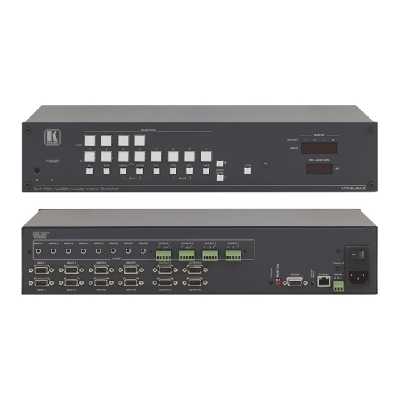
Your VP-8x4AK 8x4 VGA / UXGA / Audio Matrix Switcher Figure 1: VP-8x4AK 8x4 VGA / UXGA / Audio Matrix Switcher – Front View KRAMER: SIMPLE CREATIVE TECHNOLOGY... -
Page 11: Table 2: Front Panel Vp-8X4Ak 8X4 Vga / Uxga / Audio Matrix Switcher Features
Your VP-8x4AK 8x4 VGA / UXGA / Audio Matrix Switcher Table 2: Front Panel VP-8x4AK 8x4 VGA / UXGA / Audio Matrix Switcher Features Feature Function IR Receiver The yellow LED is illuminated when receiving signals from the infrared remote control transmitter... -
Page 12: Figure 2: Vp-8X4Ak 8X4 Vga / Uxga / Audio Matrix Switcher - Rear View
Your VP-8x4AK 8x4 VGA / UXGA / Audio Matrix Switcher Figure 2: VP-8x4AK 8x4 VGA / UXGA / Audio Matrix Switcher – Rear View KRAMER: SIMPLE CREATIVE TECHNOLOGY... -
Page 13: Using The Ir Transmitter
Your VP-8x4AK 8x4 VGA / UXGA / Audio Matrix Switcher Table 3: Rear Panel VP-8x4AK 8x4 VGA / UXGA / Audio Matrix Switcher Features Feature Function AUDIO INPUT 3.5mm Mini Connect to the unbalanced stereo audio acceptors (from 1 to 8) -
Page 14: Installing The Vp-8X4Ak In A Rack
Installing the VP-8x4AK in a Rack Installing the VP-8x4AK in a Rack This section provides instructions for rack mounting the unit. KRAMER: SIMPLE CREATIVE TECHNOLOGY... -
Page 15: Using The Vp-8X4Ak
1 You do not need to connect all inputs and outputs 2 Switch OFF the power on each device before connecting it to your VP-8x4AK. After connecting your VP-8x4AK, switch on its power and then switch on the power on each device. DO NOT push in the rear panel Flash Program “PROGRAM”... -
Page 16: Figure 3: Connecting The Vp-8X4Ak 8X4 Vga / Uxga / Audio Matrix Switcher
Using the VP-8x4AK Figure 3: Connecting the VP-8x4AK 8x4 VGA / UXGA / Audio Matrix Switcher KRAMER: SIMPLE CREATIVE TECHNOLOGY... -
Page 17: Connecting The Balanced/Unbalanced Stereo Audio Output
Figure 5: Connecting an Unbalanced Stereo Audio Output Connecting a PC or Controller to the RS-232 Port You can connect to the VP-8x4AK via an RS-232 connection using, for example, a PC. Note that a null-modem adapter/connection is not required. -
Page 18: Connecting A Pc Or Controller To The Rs 485 Port
Using the VP-8x4AK Connecting a PC or Controller to the RS 485 Port You can operate the VP-8x4AK via the RS-485 port from a distance of up to 1200m (3900ft) using any device equipped with an RS-485 port (for example, a PC). -
Page 19: Configuring The Ethernet Port
Once the machine is connected, you can configure the Ethernet port. 6.5.1 Connecting via the Ethernet You can connect the VP-8x4AK via the ETHERNET in the following ways: • For direct connection to the PC, use a crossover cable (see Section 6.5.1.1) -
Page 20: Figure 7: Local Area Connection Properties Window
Figure 8: Internet Protocol (TCP/IP) Properties Window 6.5.1.2 Connecting the ETHERNET Port via a Network Hub (Straight- Through Cable) You can connect the Ethernet port of the VP-8x4AK to the Ethernet port on a network hub or network router, via a straight-through cable with RJ-45 connectors. -
Page 21: Ethernet Port Configuration
Follow these steps to configure the port: 1. Double click the desktop icon. The Connect screen appears as follows: Figure 9: Connect Screen 2. Select the method to connect to the Ethernet port of the VP-8x4AK. Select: Ethernet, if you know the IP address number or the machine name. -
Page 22: Control Via The Ethernet Port
4. If required, make changes and press Set. If not, click Close. Control via the Ethernet Port You can control the VP-8x4AK via RS-232/RS-485 or the Ethernet using the Kramer K-Router application. If you are controlling a standalone unit via RS-232 or the Ethernet, configure the unit as master (Mach No. -
Page 23: Setting The Switching Delay Time
To exit the MACH. # mode, press the TAKE front panel button. Cascading Machines You can cascade up to 16 VP-8x4AK units with control from a PC or serial controller. To cascade up to 16 individual VP-8x4AK units via RS-485 (as illustrated in... -
Page 24: Figure 11: Control Configuration Via Rs-232 And Rs-485
4. Set the machine numbers of the connected machines, as described in Section 6.8, by set the first VP-8x4AK unit as Machine # 1 and the following 15 VP-8x4AK units as Machine # 2 to Machine # 16. 5. Set the RS-485 TERM DIP-switch ON on the first and last VP-8x4AK units (terminating the RS-485 line at 120Ω). -
Page 25: Operating The Vp-8X4Ak
2. Press an IN button to select the input to switch to the output. The selected input number appears on the 7-segment display. Incomplete operations on the VP-8x4AK timeout after 15 seconds Understanding the 7-Segment Displays The VP-8x4AK has two displays: •... -
Page 26: The Rel Audio Level 7-Segment Display
Operating the VP-8x4AK 7.2.2 The REL AUDIO LEVEL 7-Segment Display The REL AUDIO LEVEL display, as illustrated in Figure 13 (see Section 7.7). Figure 13: REL AUDIO LEVEL 7-segment Display Confirming Settings You can choose to work in the At Once or the Confirm mode. -
Page 27: Confirming A Switching Action
Operating the VP-8x4AK 7.3.2 Confirming a Switching Action To confirm a switching action (in the Confirm mode), do the following: 1. Press an OUT-IN combination. The corresponding 7-segment display blinks with the new value. The TAKE button also blinks. 2. Press the blinking TAKE button to confirm the action. -
Page 28: Recalling An Input/Output Configuration
The memory recalls the stored data from that reference. Tip: If you cannot remember which one of the eight setup configurations is the one that you want, set the VP-8x4AK to the Confirm mode and manually scan all the input/output configurations until you locate it. -
Page 29: Setting The Audio-Follow-Video Option
Operating the VP-8x4AK 7.6.1 Setting the Audio-Follow-Video Option To set the Audio-follow-video (AFV) option, press the AFV button: • If the AUDIO and VIDEO configurations are the same, then the AFV button illuminates. The audio follows the video. • If the AUDIO differs from the VIDEO, then the TAKE and the AUDIO buttons flash. -
Page 30: Flash Memory Upgrade
The latest version of firmware and installation instructions can be downloaded from the Kramer Web site at www.kramerelectronics.com. Controlling via the Embedded Web Pages You can remotely operate the VP-8x4AK using a Web browser via the Ethernet connection (see Section 9.1). -
Page 31: Connecting To The Vp-8X4Ak Via Your Browser
Controlling via the Embedded Web Pages Connecting to the VP-8x4AK via your Browser Make sure that your PC is connected via a network to the VP-8x4AK and do the following: 1. Open your Internet browser. 2. Enter the unit’s IP number or name in the Address bar of your browser. -
Page 32: The Vp-8X4Ak Switching Matrix Page
The VP-8x4AK Switching Matrix Page The VP-8x4AK switching matrix page lets you route any or all of the eight inputs to any or all of the four outputs, by clicking the audio and/or video... -
Page 33: Switch An Input To An Output Via The Embedded Web Pages
Controlling via the Embedded Web Pages Figure 19: VP-8x4AK Embedded Web Page You can perform the following operations via this Web page: • Operate in the AFV mode or switch the audio and video separately, by clicking the Audio, Video or AFV buttons (see Section 9.2.1) -
Page 34: Operate In The Confirm Mode
To confirm several actions, select several switching points and then press TAKE 4. Click the Online button to exit the Confirm mode. If you click the Online button before you click the TAKE button, the following warning appears: KRAMER: SIMPLE CREATIVE TECHNOLOGY... -
Page 35: Store And Recall Setups
Controlling via the Embedded Web Pages Figure 22: Exiting Offline Warning 9.2.3 Store and Recall Setups To store a matrix configuration: 1. From the Preset drop-down list, select a preset (for example, Preset 03). Presets that contain a configuration are displayed with a blue background; presets with no configuration have a white background. - Page 36 Offline state. The recalled configuration will become active when you press the Take button. 1 When selecting a preset that contains a configuration, the Recall button changes from gray to dark blue KRAMER: SIMPLE CREATIVE TECHNOLOGY...
-
Page 37: Audio Gain Page
Controlling via the Embedded Web Pages Figure 26: Recalling a Preset in the Confirm Mode The Help Box ? This is the main panel window. In this window you can control the channels. Audio Gain Page The AUDIO GAIN screen lets you set the gain for each of the input and output channels: Figure 27: Audio Gain To change an input or output gain, select the channel number, then click and... -
Page 38: The Configurations Page
Figure 28: CONFIGURATIONS Embedded Web Page HELP BOX ? This page lets you view and set the device configuration. 1 The model name, serial number, firmware version and MAC address 2 Or Cancel to cancel changes KRAMER: SIMPLE CREATIVE TECHNOLOGY... -
Page 39: Technical Specifications
Technical Specifications 10 Technical Specifications Table 4 lists the technical specifications: Table 4: Technical Specifications of the VP-8x4AK 8x4 Video Audio Matrix Switcher INPUTS: 8 XGA on 15-pin HD connectors (VGA through UXGA); 8 unbalanced stereo audio 3.5mm mini connectors OUTPUTS: 4 VGA on 15-pin HD connectors (VGA through UXGA);... -
Page 40: Communication Parameters
Communication Parameters 11 Communication Parameters Table 5 lists the communication parameters as used in Kramer Electronics products. Table 5: Communication Parameters EDID EDID data is passed between Output 1 and Input 1 RS-232 Protocol 2000 Protocol 3000 (Default) Baud Rate:... -
Page 41: Table Of Ascii Codes For Serial Communication (Protocol 3000)
ASCII codes that switch an input to an output for a single VP-8x4AK machine. For more detailed information, see Section 14.2. Table 6: VP-8x4AK Video Signal Codes for Protocol 3000 OUT 1 OUT 2 OUT 3 OUT 4 IN 1 #V 1>1 CR #V 1>2 CR #V 1>3 CR #V 1>4 CR... -
Page 42: Hex Codes For Serial Communication (Protocol 2000)
The Hex codes listed in this section are used to set video channels for a single machine (set as Machine 1) connected via either RS-232 or Ethernet. Similar hex codes are used when the VP-8x4AK is connected via RS-485 and the machine is set to number 2. -
Page 43: Table 12: Vp-8X4Ak Hex Codes For Increasing/Decreasing The Audio Input Gain
Hex Codes for Serial Communication (Protocol 2000) Table 12 lists the Hex codes that increase or decrease the audio input gain: Table 12: VP-8x4AK Hex Codes for Increasing/Decreasing the Audio Input Gain IN 1 IN 2 IN 3 IN 4... -
Page 44: Kramer Protocol
To switch from protocol 2000 to protocol 3000, send the following command: 0x38, 0x80, 0x83, 0x81 The Windows®-based Kramer control software operates with protocol 2000. If the VP-8x4AK is set to protocol 3000, it is automatically switched to protocol 2000. 14.2 Kramer Protocol 3000 This RS-232/RS-485 communication protocol lets you control the machine from any standard terminal software (for example, Windows®... -
Page 45: Protocol 3000 Syntax
Kramer Protocol 14.2.1 Protocol 3000 Syntax Host message format: Start Address (optional) Body Delimiter Destination_id@ message Simple command (commands string with only one command without addressing): start body delimiter Command SP Parameter_1,Parameter_2,… Commands string (formal syntax with commands concatenation and addressing): # Address@ Command_1 Parameter1_1,Parameter1_2,…... -
Page 46: Command Parts Details
Design note: transparent supporting for protocol 2000 will be implemented by switch protocol command from protocol 3000 to protocol 2000, in protocol 2000 there is already such a command to switch protocol to ASCII protocol (#56 : H38 H80 H83 H81). KRAMER: SIMPLE CREATIVE TECHNOLOGY... -
Page 47: Table 16: Instruction Codes For Protocol 3000
Response Protocol Handshaking ~OKCRLF Device initiated messages Command Syntax Start message Kramer Electronics LTD. , Device Model Version Software Version Switcher actions Audio-video channel has switched (AFV mode) AV IN>OUT Video channel has switched (Breakaway mode) VID IN>OUT Audio channel has switched (Breakaway mode) AUD IN>OUT... - Page 48 PRST-VID? PRESET, * Read audio PRST-AUD? PRESET,OUT PRST-AUD PRESET: IN>OUT connections from Short form: PAUD? PRESET,OUT saved preset PRST-AUD? PRESET, * PRST-AUD PRESET: IN>1, IN>2,… Read saved presets PRST-LST? PRST-LST PRESET, PRESET, … list Short form: PLST? KRAMER: SIMPLE CREATIVE TECHNOLOGY...
- Page 49 Numeric value (present audio processing stage). For example: "0" for Input level, "1" for Pre-Amplifier, "2" for Amplifier (Out) etc. CHANNEL = Input or Output # VOLUME = Audio parameter in Kramer units, precede minus sign for negative values. increase current value, decrease current value.
- Page 50 NET-IP IP_ADDRESS NET-IP IP_ADDRESS RESULT NTIP NET-IP? Read IP Address NET-IP IP_ADDRESS NTIP? NET-MAC? Read MAC Address NET-MAC MAC_ADDRESS NTMC Set subnet mask NET-MASK SUBNET_MASK NET-MASK SUBNET_MASK RESULT NTMSK NET-MASK? Read subnet mask NET-MASK SUBNET_MASK NTMSK? KRAMER: SIMPLE CREATIVE TECHNOLOGY...
- Page 51 Kramer Protocol Network settings commands Set gateway address NET-GATE GATEWAY_ADDRESS NET-GATE GATEWAY_ADDRESS RESULT NTGT NET-GATE? Read subnet mask NET-GATE GATEWAY_ADDRESS NTGT? Set DHCP mode NET-DHCP DHCP_MODE NET-DHCP DHCP_MODE RESULT NTDH NET-DHCP? Read subnet mask NET-DHCP DHCP_MODE NTDH? DHCP_MODE = 0 – Don't use DHCP (Use IP set by factory or IP set command).
-
Page 52: Kramer Protocol 2000
Similarly, if switching is done via the machine’s front-panel, then these bits are set with the OUTPUT NUMBER which was switched. For other operations, these bits are defined according to the table. BYTE: Bit 7 – Defined as 1. Bit 5 – Don’t care. OVR – Machine number override. M4…M0 – MACHINE NUMBER. KRAMER: SIMPLE CREATIVE TECHNOLOGY... -
Page 53: Table 18: Instruction Codes For Protocol 2000
INPUT Bit: 0 - Gain SETTINGS FOR I0 - 0=input; 1=output 1 - Bass INSTRUCTIONS 22, 24, 25 I1 - Left 2 - Treble I2 - Right 3 - Midrange 4 - Mix On CHANGE TO ASCII Kramer protocol 3000... - Page 54 This code is also returned to the PC if an RS-232 instruction is sent while the machine is being programmed via the front panel. Reception of this code by the switcher is not valid. KRAMER: SIMPLE CREATIVE TECHNOLOGY...
- Page 55 Kramer Protocol NOTE 10 – This code is reserved for internal use. NOTE 13 - This is a request to identify the switcher/s in the system. If the OUTPUT is set as 0, and the INPUT is set as 1, 2, 5 or 7, the machine will send its name.
- Page 56 EXCLUSION OF DAMAGES The liability of Kramer for any effective products is limited to the repair or replacement of the product at our option. Kramer shall not be liable for: 1. Damage to other property caused by defects in this product, damages based upon inconvenience, loss of use of the product, loss of time, commercial loss;...
- Page 57 For the latest information on our products and a list of Kramer distributors, visit our Web site: www.kramerelectronics.com, where updates to this user manual may be found. We welcome your questions, comments and feedback. Safety Warning: Disconnect the unit from the power supply before opening/servicing.
Need help?
Do you have a question about the VP-8x4AK and is the answer not in the manual?
Questions and answers