Table of Contents
Advertisement
Quick Links
Advertisement
Table of Contents

Related Manuals for Kramer VP-27


Summary of Contents for Kramer VP-27
- Page 1 Kramer Electronics, Ltd. USER MANUAL Model: VP-27 Presentation Switcher...
-
Page 2: Table Of Contents
Contents Introduction Getting Started Quick Start Overview Your VP-27 Presentation Switcher Installing the VP-27 in a Rack Connecting the VP-27 Presentation Switcher Connecting a PC Dipswitch Settings Operating the VP-27 Presentation Switcher Locking the Front Panel Resetting the VP-27 Presentation Switcher... - Page 3 Table 2: Rear Panel VP-27 Presentation Switcher Features Table 3: Dipswitch Settings (Default Setting) Table 4: Technical Specifications of the VP-27 Presentation Switcher Table 5: Hex Codes for Switching via RS-232 (Protocol 2000) Table 6: Hex Codes for Switching via RS-232 (Protocol 3000)
-
Page 4: Introduction
3 We recommend that you use only the power cord that is supplied with this machine 4 Download up-to-date Kramer user manuals from our Web site at http://www.kramerelectronics.com 5 The complete list of Kramer cables is on our Web site at http://www.kramerelectronics.com... - Page 5 Getting Started KRAMER: SIMPLE CREATIVE TECHNOLOGY...
-
Page 6: Overview
A LOCK button to prevent tampering with the front panel Control the VP-27 via the front panel buttons or IR remote control using the Kramer infrared remote control transmitter (provided) or by RS-232 serial commands transmitted by a touch screen system, PC, or other serial controller. -
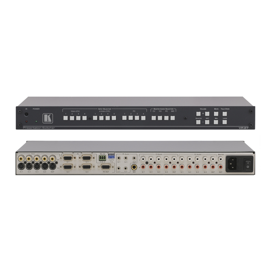
Page 7: Figure 1: Vp-27 Presentation Switcher
Your VP-27 Presentation Switcher Figure 1: VP-27 Presentation Switcher KRAMER: SIMPLE CREATIVE TECHNOLOGY... -
Page 8: Table 1: Front Panel Vp-27 Presentation Switcher Features
Your VP-27 Presentation Switcher Table 1: Front Panel VP-27 Presentation Switcher Features Feature Function IR Receiver Signals from the remote control transmitter illuminate the LED POWER LED Lights when the unit is turned ON INPUT VIDEO (CV) Select the composite video / audio input (from 1 to 4) -
Page 9: Table 2: Rear Panel Vp-27 Presentation Switcher Features
Your VP-27 Presentation Switcher Table 2: Rear Panel VP-27 Presentation Switcher Features Feature Function Video Y/C IN 4-pin Connect to the s-Video sources Connectors CV IN RCA Connect to the composite video sources Y/C OUT 4-pin Connect to the s-Video acceptor... -
Page 10: Installing The Vp-27 In A Rack
Installing the VP-27 in a Rack Installing the VP-27 in a Rack This section describes what to do before installing in a rack and how to rack mount. Before Installing in a Rack How to Rack Mount Before installing in a rack, be sure that the environment is... -
Page 11: Connecting The Vp-27 Presentation Switcher
However, you do not need to connect all the inputs and outputs 2 Switch OFF the power on each device before connecting it to your VP-27. After connecting your VP-27, switch on its power and then switch on the power on each device... -
Page 12: Figure 2: Connecting The Vp-27
Connecting the VP-27 Presentation Switcher Figure 2: Connecting the VP-27... -
Page 13: Connecting A Pc
To connect a PC to a VP-27 unit, connect the RS-232 terminal block connector on the VP-27 unit to the RS-232 9-pin D-sub port on your PC, see Figure 3: RS-232 to VP-27 PIN 5 Connected to G... -
Page 14: Operating The Vp-27 Presentation Switcher
One of the four s-Video (Y/C) inputs to the s-Video output One of the four PC inputs to the PC output of the VP-27 The selected button in each group is illuminated in red An audio input can be switched to the master audio output either by pressing... -
Page 15: Resetting The Vp-27 Presentation Switcher
8.2 Connecting the PC to the RS-232 Port Before installing the latest Kramer firmware version on a VP-27 unit, connect the RS-232 9-pin D-sub rear panel port on the VP-27 unit to your PC. 8.3 Upgrading Firmware Follow these steps to upgrade the firmware: 1. -
Page 16: Figure 5: Flashloader Window
4. Click the Send Bin File button. The following window appears: Loading the Latest Firmware 5. Select the latest VP-27 firmware version, and click Open. Wait for completion of the upgrade procedure. The new firmware version appears in the INPUT STATUS 7-segment Display. -
Page 17: Figure 6: Flash Upgrade Process
Firmware Upgrade Figure 6: Flash Upgrade Process 6. If required, disconnect the RS-232 rear panel port on the VP-27 unit from the KRAMER: SIMPLE CREATIVE TECHNOLOGY... -
Page 18: Technical Specifications
Technical Specifications Technical Specifications Table 4 includes the technical specifications: Table 4: Technical Specifications of the VP-27 Presentation Switcher INPUTS: 4 composite video on RCA connectors 4 s-Video on 4-pin connectors 4 PC on 15-pin HD connectors 4 unbalanced stereo audio on RCA connectors, L+R (for CV) 4 unbalanced stereo audio on RCA connectors, L+R (for Y/C) 4 unbalanced stereo audio on 3.5mm jack connectors (for PC) -
Page 19: Table Of Hex Codes For Serial Communication
Table of Hex Codes for Serial Communication 10 Table of Hex Codes for Serial Communication Table 5 lists the Protocol 2000 Hex values for the VP-27: Table 5: Hex Codes for Switching via RS-232 (Protocol 2000) MASTER AUDIO IN 1... -
Page 20: Kramer Protocol
Kramer Protocol 11 Kramer Protocol By default, the VP-27 is set to protocol 3000 (see section 11.3) but is also compatible with Kramer’s Protocol 2000 (see section 11.4). Section 11.2 describes how to switch between protocol 3000 and protocol 2000. -
Page 21: Kramer Protocol 3000
Sequence of Alfa-Numeric ASCII chars (' 0' -' 9' ,' A' -' Z' ,' a' -' z' and some special chars for specific commands), parameters will be separated by commas. 1 Not available at the time of printing. Refer to our Web site at http://www.kramerelectronics.com for details KRAMER: SIMPLE CREATIVE TECHNOLOGY... -
Page 22: Table 7: Instruction Codes For Protocol 3000
Response Protocol Handshaking ~OKCRLF Device initiated messages Command Syntax Start message Kramer Electronics LTD. , Device Model Version Software Version Switcher actions Audio-video channel has switched (AFV mode) AV IN>OUT Video channel has switched (Breakaway mode) VID IN>OUT Audio channel has switched (Breakaway mode) - Page 23 AUD IN>1, IN>2, … AUD? * Parameters Description: IN = Input number or '0' to disconnect output. > ' = Connection character between in and out parameters. OUT = Output number or '*' for all outputs. KRAMER: SIMPLE CREATIVE TECHNOLOGY...
- Page 24 Kramer Protocol Examples: Switch Video and Audio input 3 to output 7 #AV 3>7CR ~AV 3>7 OKCRLF Switch Video input 2 to output 4 #V 2>4CR ~VID 2>4 OKCRLF Switch Video input 4 to output 2 in #6@VID 4>2CR ~6@VID 4>2 OKCRLF...
- Page 25 Kramer Protocol CHANNEL = Input or Output # VOLUME = Audio parameter in Kramer units, precede minus sign for negative values. increase current value, decrease current value. Machine info commands Command Syntax Response * Time settings commands require admin authorization...
-
Page 26: Kramer Protocol 2000
Kramer Protocol 11.4 Kramer Protocol 2000 This RS-232 communication protocol uses four bytes of information as defined below. The default data rate is 9600 baud, with no parity, 8 data bits and 1 stop bit. Table 8: Protocol Definitions DESTI-... -
Page 27: Table 9: Instruction Codes For Protocol 2000
4 - Mix On INSTRUCTIONS 22, 24, 25 I1 - Left I2 - Right CHANGE TO ASCII 3 - Kramer protocol 3000 IDENTIFY MACHINE 1 - video machine name 0 - Request first 4 digits 2 - audio machine name... - Page 28 Kramer Protocol NOTE 2 - These are bi-directional definitions. That is, if the switcher receives the code, it will perform the instruction; and if the instruction is performed (due to a keystroke operation on the front panel), then these codes are sent. For example, if the HEX code was sent from the PC, then the switcher (machine 3) will switch input 5 to output 8.
- Page 29 (in real-time). For example, if input 3 is detected as invalid, the unit will send the HEX codes If input 7 is detected as valid, then the unit will send HEX codes KRAMER: SIMPLE CREATIVE TECHNOLOGY...
- Page 30 EXCLUSION OF DAMAGES The liability of Kramer for any effective products is limited to the repair or replacement of the product at our option. Kramer shall not be liable for: 1. Damage to other property caused by defects in this product, damages based upon inconvenience, loss of use of the product, loss of time, commercial loss;...
- Page 31 For the latest information on our products and a list of Kramer distributors, visit our Web site: www.kramerelectronics.com, where updates to this user manual may be found. We welcome your questions, comments and feedback. Safety Warning: Disconnect the unit from the power supply before opening/servicing.
Need help?
Do you have a question about the VP-27 and is the answer not in the manual?
Questions and answers