
Subscribe to Our Youtube Channel
Related Manuals for Owon HDS2202


Summary of Contents for Owon HDS2202
- Page 1 HDS200 Dual Channel Series Handheld Oscilloscope Quick Guide ◼ HDS272(S) ◼ HDS242(S) ◼ HDS2102(S) ◼ HDS2202(S) For product support, visit: www.owon.com.hk/download...
- Page 2 LILLIPUT Company. Fujian LILLIPUT Optoelectronics Technology Co., Ltd. No. 19, Heming Road Lantian Industrial Zone, Zhangzhou 363005 P.R. China Tel: +86-596-2130430 Fax: +86-596-2109272 Web: www.owon.com E-mail: info@owon.com.cn...
- Page 3 General Warranty We warrants that the product will be free from defects in materials and workmanship for a period of 3 years from the date of purchase of the product by the original purchaser from the our Company. The warranty period for accessories such as probes, adapter is 12 months.
-
Page 4: Table Of Contents
SAFETY INFORMATION · · · · · · · · · · · · · · · · · · · · · · · · · · · · · · · · · · · · · · · · · · · · · · · · · · · · · · · · · · · · 1 HOW TO IMPLEMENT THE GENERAL INSPECTION ·... -
Page 5: Safety Information
1. Safety Information (Before using this product, please read the safety information in advance) Safety Terms Terms in this manual (The following terms may appear in this manual): Warning: Warning indicates conditions or practices that could result in injury or loss of life. Caution: Caution indicates the conditions or practices that could result in damage to this product or other property. - Page 6 Warning: To prevent electric shock or fire, use a suitable power adapter. Only power adapters that are dedicated to this product and approved for use in the country of use may be used. Warning: The two channels of the oscilloscope are non-isolated channels. Note that the channel should use a common reference when measuring, and the ground wires of the two probes cannot be connected to two non-isolated places with different DC electrical levels, otherwise it may cause a short circuit due to the...
- Page 7 powered computer through the port, it is not allowed to measure the primary power supply of power grid. Warning: If the input port of the oscilloscope is connected to a voltage with a peak value higher than 42V (30vrms) or a circuit with a peak value of more than 4800 VA, the following measures shall be taken to avoid electric shock or fire: ⚫...
-
Page 8: How To Implement The General Inspection
refers to the level. Level II is the low voltage and high energy level, which refers to the local electrical level applicable to electrical appliances and portable equipment. ⚫ Do not input any electric such as signal, voltage or current into the GEN O ut port of the signal generator. -
Page 9: How To Use The Oscilloscope
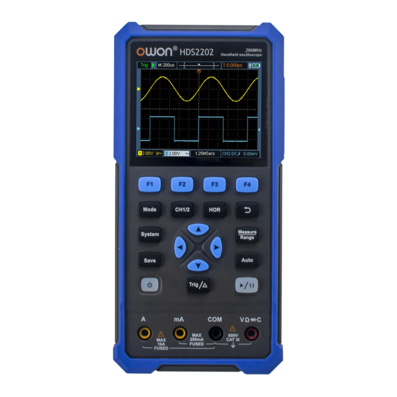
Check the Complete Instrument If it is found that there is damage to the appearance of the instrument, or the instrument can not work normally, or fails in the performance test, please get in touch with our distributor responsible for this business or our local offices. If there is damage to the instrument caused by the transportation, please keep the package. - Page 10 Figure 4: Front Panel of the Oscilloscope Description: 1. CH1 and CH2 input connectors. 2. Waveform generator output connector (optional). 3. Display area. 4. The F1 - F4 keys are multi-function keys. In each menu mode, press the corresponding key to select the corresponding menu item. 5.
-
Page 11: Side Panel
14. Enter the save settings key. 15. Enter the system settings key. 16. Switch key for working state of oscilloscope and multimeter. 17. CH1 / CH2 - channel switch key. Side Panel Description: 1. Probe compensation: 3.3V/1kHz square wave signal output 2. -
Page 12: Introduction To The User Interface Of The Oscilloscope
Introduction to the User Interface of the Oscilloscope 1 2 3 Figure 5: Oscilloscope Interface Description: 1. The trigger status indicates the following information: Auto: Automatic mode. The waveform is being collected without triggering. Trig: A trigger has been detected and post trigger information is being collected. -
Page 13: Functional Check
8. Battery power and external power supply indication. 9. Channel 1 waveform. 10. The pointer indicates the trigger electrical level position of the channel. 11. Channel 2 waveform. 12. The icon indicates trigger-related information, including trigger channel, coupling mode, trigger type and trigger electrical level. 13. -
Page 14: Probe Compensation
the CH1 channel. Align the slot on the probe with the plug on the bayonet nut connector (BNC) of the CH1 connector and insert it, then turn the probe to the right and tighten it. Connect the probe tip and ground clamp to the connector of the probe compensator. -
Page 15: Probe Attenuation Coefficient Setting
connector of the probe compensator, and then press the Auto key on the front panel. 2. Check the displayed waveform and adjust the probe until the compensation is correct. See Figure 0-2 and Figure 0-3. Overcompensation Correct compensation Under-compensation Figure 0-2: Display Waveform of Probe Compensation 3. -
Page 16: Safe Use Of Probe
Note: The preset setting of the probe attenuation coefficient in the menu when the oscilloscope is delivered is 10X. Make sure that the attenuation switch setting value on the probe is the same as the probe attenuation coefficient option in the oscilloscope menu. -
Page 17: How To Use The Multimeter
Warning: To prevent electric shock when using the probe, please keep your fingers behind the safety ring on the probe body. To prevent electric shock when using the probe, do not touch the metal part of the probe head when the probe is connected to a voltage source. - Page 18 Multimeter Interface Description: 1. Measurement type indication: ------ DC voltage measurement ~ ACV ------ AC voltage measurement ------ DC current measurement ~ ACA ------ AC current measurement Resist ------ Resistance measurement Diode ------ Diode measurement Cont ------ On/Off measurement ------ Capacitance measurement 2.Range indication: Manual means manual range;...
- Page 19 9. The selected range V or mV in voltage measurement; the selected current range A or mA in current measurement. 10. To choose AC or DC voltage measurement. 11. To choose to AC or DC current measurement. 12. Display of relative value measurement function (only available when measuring DC current, DC voltage and resistance).
-
Page 20: How To Use The Waveform Generator(Optional
5. How to Use the Waveform Generator(optional) The instrument can provide 4 basic waveforms, sine wave, square wave, ramp wave, pulse wave, and 8 arbitrary waveforms. Connect the output Press the Mode button to switch the instrument interface to the waveform generator function interface. -
Page 21: Troubleshooting
6. Troubleshooting 1. The oscilloscope cannot be turned on. It may be that the battery is completely exhausted. At this time, even if the oscilloscope is powered by the power adapter, the oscilloscope cannot be turned on. You need to charge the battery first, and do not turn on the oscilloscope. -
Page 22: Appendix
Appendix A: List of Accessories ⚫ 1 USB cable ⚫ 1 passive probes ⚫ 1 crocodile clip cable (HDS242/HDS272/HDS2102/HDS2202) ⚫ 2 crocodile clip cable (HDS242S/HDS272S/HDS2102S/HDS2202S) ⚫ 1 set of multimeter probes (one red and one black) ⚫ 1 user manual ⚫... - Page 23 Cleaning: Check the instrument and probe frequently according to the operation. Clean the external surface of the instrument as follows: 1. Please wipe the floating dust outside the instrument and probe with a soft cloth. When cleaning the LCD, be careful not to scratch the transparent LCD protection screen.
- Page 24 the screen are explained as follows: symbol indicates the power-on charging status; symbol indicates battery power supply; symbol indicates that there is only about five minutes of use time left. Please charge as soon as possible according to the relevant tips to avoid damage to the battery.
Need help?
Do you have a question about the HDS2202 and is the answer not in the manual?
Questions and answers