Table of Contents
Advertisement
Quick Links
52059725 REV 10
1.800.561.8187
INSTRUCTION MANUAL
UT10 Ultra Tugger
Cable Puller and
Pulling Packages
Serial Codes ANB and BBD
Read and understand all of the instructions and
safety information in this manual before operating
or servicing this tool.
www.
© 2020 Greenlee Tools, Inc.
.com
Español ............... 37
Français .............. 73
®
information@itm.com
3/20
Advertisement
Table of Contents

Related Manuals for Textron Greenlee Ultra Tugger UT10-2S


Summary of Contents for Textron Greenlee Ultra Tugger UT10-2S
- Page 1 INSTRUCTION MANUAL Español ....37 Français ....73 UT10 Ultra Tugger ® Cable Puller and Pulling Packages Serial Codes ANB and BBD Read and understand all of the instructions and safety information in this manual before operating or servicing this tool. 52059725 REV 10 ©...
-
Page 2: Table Of Contents
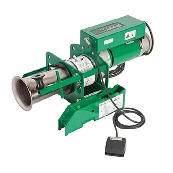
® Ultra Tugger 10 Cable Puller and Pulling Packages Table of Contents Description ® Description ..............2 The Greenlee UT10 Ultra Tugger Cable Puller is intended to be used to pull cable through conduit and in Safety ................2 tray. The UT10 will develop 44.5 kN (10,000 lb) of pulling Purpose of this Manual .......... -
Page 3: General Safety Rules
® Ultra Tugger 10 Cable Puller and Pulling Packages GENERAL SAFETY RULES Avoid accidental starting. Be sure switch is off WARNING! Read and understand all instructions. before plugging in. Carrying tools with your finger on Failure to follow all instructions listed below may result the switch or plugging in tools that have the switch on in electric shock, fire, and/or serious personal injury. -
Page 4: Specific Safety Rules And Symbols
® Ultra Tugger 10 Cable Puller and Pulling Packages SPECIFIC SAFETY RULES AND SYMBOLS SAFETY ALERT Do not operate the cable puller in a hazardous environment. Hazards SYMBOL include flammable liquids and gases. Failure to observe this warning will result in severe injury or death. This symbol is used to call your attention to hazards or unsafe practices which could result in an injury or property damage. - Page 5 ® Ultra Tugger 10 Cable Puller and Pulling Packages SPECIFIC SAFETY RULES AND SYMBOLS Inspect and verify the maximum Locate the puller so that it is close to the conduit. load-bearing capacity or maximum Rope, cable, or connectors can break under tension, strength of all structural supports, causing the rope to whip violently.
- Page 6 ® Ultra Tugger 10 Cable Puller and Pulling Packages SPECIFIC SAFETY RULES AND SYMBOLS • Check the condition of the entire rope before use. Rope, cable, or a connecting device can break under A worn or damaged rope can break under tension tension, causing the rope to whip violently.
-
Page 7: Grounding Instructions
® Ultra Tugger 10 Cable Puller and Pulling Packages SPECIFIC SAFETY RULES AND SYMBOLS Inspect puller and accessories before use. Replace When using the wheeled carriage to transport the any worn or damaged components with Greenlee UT10: replacement parts. A damaged or improperly assem- •... -
Page 8: Functional Description Identification
® Ultra Tugger 10 Cable Puller and Pulling Packages FUNCTIONAL DESCRIPTION Identification UT10 Cable Puller 7. Hitch Clip 1. Motor 8. Rope Tie-Off 2. Circuit Breaker/Switch 9. Right Angle Sheave 3. Power Cord 10. Tapered Steel Capstan 4. Force Gauge 11. - Page 9 ® Ultra Tugger 10 Cable Puller and Pulling Packages Identification (cont’d) Mobile Carriage and Boom 1. Puller 2. Elbow 3. Nose 4. Back Boom 5. Forward Boom 6. Detent Pin 7. Crank 8. Conduit Adapter Couplings 9. Adapter Storage Hanger 10.
-
Page 10: Specifications
® Ultra Tugger 10 Cable Puller and Pulling Packages Specifications Weight ......................38 kg (84 lb) Dimensions Length ....................29 cm (11.5") Width ....................... 66 cm (26") Height ....................17 cm (6.75") Motor Voltage ............120/230 VAC, 50/60 Hz, single phase Current Draw at Full Load ........ -
Page 11: Cable Pulling Glossary
® Ultra Tugger 10 Cable Puller and Pulling Packages Cable Pulling Glossary anchoring system resultant force any item or group of items that keeps a cable pulling any force that is produced when two or more forces act component in place during the cable pull on an object;... -
Page 12: Cable Pulling Principles
® Ultra Tugger 10 Cable Puller and Pulling Packages Cable Pulling Principles Cable Pulling Systems Pulling cable is a complex process. This section of the manual describes and explains four main topics of Pulling cable requires a system of components. At a pulling cable: minimum, a cable pulling system will include a cable •... -
Page 13: Pulling Theory
® Ultra Tugger 10 Cable Puller and Pulling Packages Cable Pulling Principles (cont’d) Pulling Theory To accomplish a cable pull, the cable pulling system must develop more force than the combination of This section introduces the main ideas involved with gravity and friction. -
Page 14: Cable Pulling Forces
® Ultra Tugger 10 Cable Puller and Pulling Packages Cable Pulling Principles (cont’d) Cable Pulling Forces At the Cable Puller Anchoring System The cable puller will exert its maximum pulling force on This section provides detailed explanations and illustra- cable puller’s anchoring system. It is extremely impor- tions of the forces that are generated during the cable tant the anchoring system can withstand this amount of pull. - Page 15 ® Ultra Tugger 10 Cable Puller and Pulling Packages Cable Pulling Principles (cont’d) Cable Pulling Forces (cont’d) The following table is based on the formula above. The input, or tailing force, is constant at 44.5 N (10 lb). At the Capstan Increasing the number of wraps increases the pulling force.
- Page 16 ® Ultra Tugger 10 Cable Puller and Pulling Packages Cable Pulling Principles (cont’d) Cable Pulling Forces (cont’d) A similar double-braided composite rope could store approximately 300,000 joules of energy. This could At the Pulling Rope throw the same object only 34 meters into the air. The double-braided composite rope stores much less The product of a force (f) moving through a distance energy and has much less potential for injury if it were...
- Page 17 ® Ultra Tugger 10 Cable Puller and Pulling Packages Cable Pulling Principles (cont’d) Cable Pulling Forces (cont’d) When selecting a pulling grip, it is extremely important to select a grip of the correct (1) type, (2) size, and At the Connectors (3) maximum rated capacity.
- Page 18 ® Ultra Tugger 10 Cable Puller and Pulling Packages Cable Pulling Principles (cont’d) Cable Pulling Forces (cont’d) Resultant Force Table (35.6 kN or 8,000 lb Pulling Force) At the Sheaves Angle of Change Resultant Force Sheaves are used to change the direction of the pull. Illustration in Direction in kN (lb)
-
Page 19: Tailing The Rope
® Ultra Tugger 10 Cable Puller and Pulling Packages Cable Pulling Principles (cont’d) Tailing the Rope Number of Wraps of Rope Around the Capstan An experienced operator should choose the number The rope must be pulled off of the capstan as the pull times the rope is wrapped around the capstan. -
Page 20: Summary Of Cable Pulling Principles
® Ultra Tugger 10 Cable Puller and Pulling Packages Cable Pulling Principles (cont’d) Planning the Pull Summary of Cable Pulling Principles • Pull in a direction that will require the lowest amount of pulling force. • A cable pulling system consists of many components •... -
Page 21: Assembly
® Ultra Tugger 10 Cable Puller and Pulling Packages ASSEMBLY Boom Assembly/Disassembly 4. Pull out on the detent ring that locks the boom tube, and twist the nose slightly so the hole in the boom tube and detent pin are misaligned. Under normal circumstances, there is no need to disas- semble the boom assembly. -
Page 22: Boom Setup
® Ultra Tugger 10 Cable Puller and Pulling Packages Boom Setup Up Pull Starting from Teepee Position To use slip-in couplings: a. Insert the appropriate slip-in conduit adapter 1. Set the brakes. coupling into the nose. 2. Raise the forward boom as described under “Boom b. -
Page 23: Down Pull Starting From Teepee Position
® Ultra Tugger 10 Cable Puller and Pulling Packages Boom Setup (cont’d) Down Pull Starting from Teepee Position 4. Lower the entire boom until the forward boom is close to vertical. 1. Set the brakes. 5. Lower the forward boom until the elbow is close to 2. -
Page 24: Horizontal Pull
® Ultra Tugger 10 Cable Puller and Pulling Packages Boom Setup (cont’d) Horizontal Pull Single Boom Pull Horizontal pulls are essentially the same as an up pull or All of the previous boom setup instructions assume that a down pull. two booms are used. -
Page 25: Boom Components
® Ultra Tugger 10 Cable Puller and Pulling Packages Boom Setup (cont’d) Boom Components Use these boom tubes only: • Boom tubes supplied with the UT10 • 3" rigid steel conduit (3 m or 10' maximum) • 3" Schedule 40 pipe (3 m or 10' maximum) •... -
Page 26: Transporting The Boom
® Ultra Tugger 10 Cable Puller and Pulling Packages Transporting the Boom Wheeling Lifting 1. If the unit had been set up for an up pull: 1. Connect a lifting sling to the top puller head mount- ing pin. a. Lower the nose to the floor to get to the Teepee transport position. -
Page 27: Operation Boom Operation
® Ultra Tugger 10 Cable Puller and Pulling Packages OPERATION Boom Operation Pivoting the Elbow and Nose Units The elbow and nose units are physically identical and Raising and Lowering can be used interchangeably. For the sake of clarity, in this manual: The boom can be raised and lowered using the crank •... - Page 28 ® Ultra Tugger 10 Cable Puller and Pulling Packages Boom Operation (cont’d) Boom Tubes Conduit Adapter Couplings The pulling system comes standard with a 4' and 3' long Couplings to attach the puller system to the conduit are boom. The default setup is with the 3' boom between available in 2", 2-1/2", 3", 3-1/2", 4", and 5"...
-
Page 29: Puller Operation
® Ultra Tugger 10 Cable Puller and Pulling Packages Puller Operation 1. Fish the rope through the conduit. 6. After the foot switch is depressed, the green light indicating 0 lb will be lit. As the force climbs, an 2. Set up the cable puller. Refer to the illustrations and additional light illuminates for every 1000 lb increase instructions in the “Typical Setups”... -
Page 30: Removing Cable
® Ultra Tugger 10 Cable Puller and Pulling Packages Removing Cable Puller Placement Removing old cable involves the same principles as installing new cable. However, there are some important Pulling out old cable is generally accomplished with the differences. puller located some distance away from the end of the conduit. -
Page 31: Service
® Ultra Tugger 10 Cable Puller and Pulling Packages SERVICE Tool service must be performed only by qualified Switchbox Assembly Notes repair personnel. Service or maintenance performed by 1. The ribbon cable has an arrow at the No. 1 pin unqualified personnel could result in a risk of injury. - Page 32 ® Ultra Tugger 10 Cable Puller and Pulling Packages Maintenance (cont’d) Right Angle Sheave Bracket Removal Disassembly of Planet Gear Carriers 1. Remove detent pin. 1. Remove the flat head screws. 2. Slide arm towards motor. Use a small punch to 2.
-
Page 33: Accessories
® Ultra Tugger 10 Cable Puller and Pulling Packages ACCESSORIES Chain Mount—Secured to Steel Conduit or Pipe Floor Mount—Secured to a Concrete Floor Greenlee Tools, Inc. 1.800.561.8187 information@itm.com www. .com... -
Page 34: Setup-Chain Mount
® Ultra Tugger 10 Cable Puller and Pulling Packages Setup—Chain Mount Requires: Exposed metallic conduit with the following characteristics: • 63.5 mm to 254 mm (2-1/2" to 10") in diameter Do not pull between the 10 o’clock and 2 o’clock •... - Page 35 ® Ultra Tugger 10 Cable Puller and Pulling Packages Setup—Chain Mount (cont’d) 1. On each vise chain unit: a. Rotate the vise chain handle counterclockwise to expose most of the threads. Leave only three or four threads engaged in the handle. b.
-
Page 36: Setup-Floor Mount
® Ultra Tugger 10 Cable Puller and Pulling Packages Setup—Floor Mount Installation Requires: A concrete floor with the following characteristics: Greenlee recommends using Greenlee 35607 Wedge • Fully cured structural-type concrete Anchors. If another type of anchor is used, they must have an ICBO (International Conference of Building •...
Need help?
Do you have a question about the Greenlee Ultra Tugger UT10-2S and is the answer not in the manual?
Questions and answers