Table of Contents
Advertisement
Quick Links
ALTENERGY POWER SYSTEM Inc.
latam.APsystems.com
APsystems Guadalajara:
AV. Lazaro Cardenas 2850-5º Piso, Colonia Jardines del Bosque
P. 44520, Guadalajara, Jalisco
TEL: 52 (33) -3188-4604
Installation / User Manual
APsystems QS1A Microinverter
EMAIL: info.latam@APsystems.com
(For LATAM)
Please scan the QR code to
get mobile app and more
support
to
help
the
installation.
© All Rights Reserved
Advertisement
Table of Contents
Troubleshooting

Subscribe to Our Youtube Channel
Related Manuals for APsystems QS1A


Summary of Contents for APsystems QS1A
- Page 1 Installation / User Manual APsystems QS1A Microinverter (For LATAM) Please scan the QR code to get mobile app and more support help installation. ALTENERGY POWER SYSTEM Inc. latam.APsystems.com © All Rights Reserved APsystems Guadalajara: AV. Lazaro Cardenas 2850-5º Piso, Colonia Jardines del Bosque P.
-
Page 2: Table Of Contents
4.4.4 Step 4 - Ground the system....................10 4.4.5 Step 5 - Connect the APsystems microinverter to AC bus cable......10 4.4.6 Step 6 - Install a AC bus protective end cap at the end of AC bus cable......10 4.4.7 Step 7 - Connect APsystems Microinverters to the PV Modules...... -
Page 3: Important Safety Instructions
Be aware that the case of the APsystems Microinverter is the heat sink and can reach a temperature of 80°C. To reduce risk of burns, do not touch the case of the Microinverter. Do NOT attempt to repair the APsystems Microinverter. If it fails, contact APsystems ... -
Page 4: Radio Interference Statement
EMC and is authorized to energize, ground, and tag equipment, systems, and circuits in accordance with established safety procedures. The inverter and complete system may only be commissioned and operated by qualified personnel. APsystems QS1A Installation/User Manual... -
Page 5: Apsystems Microinverter System Introduction
2. APsystems Microinverter System Introduction The APsystems Microinverter is used in utility-interactive grid-tied applications, comprised of three key elements: APsystems Microinverter APsystems Energy Communication Unit (ECU) APsystems Energy Monitor and Analysis (EMA) web-based monitoring and analysis system... - Page 6 PV modules in the array. When PV modules in the array are affected by shade, dust, orientation, or any situation in which one module underperforms compared with the other units, the APsystems Microinverter ensures top performance from the array by maximizing the performance of each module within the array.
-
Page 7: Apsystems Microinverter Qs1A Introduction
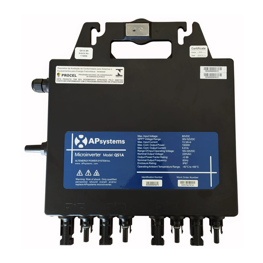
3. APsystems Microinverter QS1A Introduction The APsystems QS1A Microinverter connect to single phase grid and can also be configured for 3-phase grid, and operates with most 60 and 72 cell PV modules. Contact APsystems Customer Support for checking compatibility. For more information, please see the Technical Data page (p.17) of this manual. -
Page 8: Apsystems Microinverter System Installation
Special Statement! An AC GFCI device should not be used to protect the dedicated circuit to the APsystems microinverter even though it is an outside circuit. None of the small GFCI devices (5mA-30 mA) are designed for back feeding and will be damaged if back feed. In a similar manner, AC AFCIs have not been evaluated for back feeding and may be damaged if back feed with the output of a PV inverter. -
Page 9: Pv Rapid Shut Down Equipment
4. APsystems Microinverter System Installation 4.3 PV Rapid Shut Down Equipment This product is PV Rapid Shut Down Equipment and conforms with NEC-2014 and NEC-2017 section 690.12, for AC and DC conductors, when installed according to the following requirements: ... -
Page 10: Installation Procedures
Forbidden to hand carry the inverter through AC cable. Figure 2 4.4.3 Step 3 - Attach the APsystems Microinverters to the racking a. Mark the location of the microinverter on the rack, taking into acount the position of the PV module junction box or any other obstructions. -
Page 11: Step 4 - Ground The System
Figure 4 4.4.5 Step 5 - Connect the APsystems microinverter to AC bus cable Push the microinverter AC connector into the trunk cable connector until you hear a "click". Try to remove it to check that it is properly locked. -
Page 12: Step 7 - Connect Apsystems Microinverters To The Pv Modules
PV connections. a. Each APsystems Microinverter has removable serial number labels. b. Peel labels off, affix one to the respective location on the APsystems installation map,and fill in 1,2 in the label below,according to the layout on the roof. - Page 13 Peel the label and affix it to the respective location on the The APsystems Installation Map is a diagram of the physical location of each microinverter in your PV installation. APsystems installation map. Each APsystems microinverter has a removable serial number label located on the mounting plate. Pee l the label and affix it to the respective location on the APsystems installation map.
-
Page 14: Apsystems Microinverter System Operating Instructions
Plug in the ECU and follow the instructions according to the manual for the ECU. The APsystems Microinverters will start to send performance data over ZigBee to the ECU. The time required for all the Microinverters in the system to report to the ECU will vary with the number of Microinverters in the system. -
Page 15: Troubleshooting
Always disconnect AC power before disconnecting the PV module wires from the APsystems Microinverter. The APsystems Microinverter is powered by PV module DC power. AFTER disconnecting the DC power, when reconnecting the PV modules to the microinverter, be sure to watch for the three short LED flashes. -
Page 16: Troubleshooting A Non-Operating Apsystems Microinverter
Verify the PV module DC voltage is within the allowable range shown in the Technical Data of this manual. If the problem persists, please call APsystems Customer Support. Do not attempt to repair the APsystems Microinverter. If troubleshooting methods fail, please return the microinverter to your distributor for replacement. 6.3 Maintenance No need to Maintenance. -
Page 17: Replace A Microinverter
7. Replace a microinverter Follow the procedure to replace a failed APsystems Microinverter A. Disconnect the APsystems Microinverter from the PV Module, in the order shown below: 1. Disconnect the inverter AC connector from the AC Bus. 2. Disconnect the first AC connector in the branch circuit. -
Page 18: Technical Data
APsystems website www.APsystems.com. You must match the DC operating voltage range of the PV module with the allowable input voltage range of the APsystems Microinverter. The maximum open circuit voltage of the PV module must not exceed the specified... -
Page 19: Qs1A Microinverter Datasheet
Certificate & Compliance ABNT NBR 16149:2013; UL1741 (IEEE1547); CSA Compliance ABNT NBR 16150:2013; C22.2 No. 107.1; NOM-001 ABNT NBR IEC 62116: 2012 PLEASE NOTE QS1A IS NOT CERTIFIED FOR USA(not CEC listed, not CA Rule 21/IEEEE2030.5) APsystems QS1A Installation/User Manual... - Page 20 < 59.3 0.16 +/-200ms *APsystems online Energy Management Analysis (EMA) platform Specifications subject to change without notice - please ensure you are using the most recent update found at www.APsystems.com © All Rights Reserved 2021/02/19 Rev1.2 APsystems QS1A Installation/User Manual...
-
Page 21: Wiring Diagram
9. Wiring Diagram 9.1 Single-phase wiring diagram (LATAM) Figure11 QS1A Installation/User Manual... -
Page 22: Sample Wiring Diagram - 120D 208 3-Phase Grid (Latam)
9. Wiring Diagram 9.2 Sample Wiring Diagram - 120D 208 3-Phase Grid (LATAM) QS1A Figure12 QS1A Installation/User Manual... -
Page 23: Sample Wiring Diagram - 120Y 208 3-Phase Grid (Latam)
9. Wiring Diagram 9.3 Sample Wiring Diagram - 120Y 208 3-Phase Grid (LATAM) QS1A Figure13 QS1A Installation/User Manual... -
Page 24: Single-Phase Wiring Diagram (Brazil)
9.Wiring Diagram 9.4 Single-phase wiring diagram (Brazil) SOLAR PANEL BROWN - L BLUE - N YELLOW GREEN - PE AC JUNCTION BOX ENERGY COMMUNICATION UNIT DISTRIBUTION BOX Figure14 QS1A Installation/User Manual... -
Page 25: Qs1A Accessory
5.Bus Cable Unlock Tool . 1 Bus Cable Grid 3.Bus Cable End Cap 4.Bus Cable Y CONN Cap 10.DC Extension Cable 6.DC Male Connector Cap 7.DC ale Connector Cap 2.AC Branch Extension Cable 11.Energy Communication Unit APsystems QS1A Installation/User Manual... -
Page 26: Accessories Summary (Latam)
2300531032 25A AC Male Connector (EN,3-wire) (Optional) AC Connector (Female) 2300532032 25A AC Female Connector (EN,3-wire) (Optional) 2310310274 1m DC Extension Cable(MC4) DC Extension Cable (Optional) 2310360214 2m DC Extension Cable(MC4) Energy Communication —— ECU-R(ECU-C) Unit(Optional) APsystems QS1A Installation/User Manual... -
Page 27: Accessories Summary (Brazil)
2300531032 25A AC Male Connector (EN,3-wire) (Optional) AC Connector (Female) 2300532032 25A AC Female Connector (EN,3-wire) (Optional) 2310310274 1m DC Extension Cable(MC4) DC Extension Cable (Optional) 2310360214 2m DC Extension Cable(MC4) Energy Communication —— ECU-R(ECU-C) Unit(Optional) APsystems QS1A Installation/User Manual... - Page 28 The APsystems Installation Map is a diagram of the physical location of each microinverter in your PV installation. Each APsystems microinverter has a removable serial number label located on the mounting plate. Peel the label and affix it to the respective location on the APsystems installation map.
Need help?
Do you have a question about the QS1A and is the answer not in the manual?
Questions and answers