
Related Manuals for Volvo Penta D34A MS


Summary of Contents for Volvo Penta D34A MS
- Page 1 OPERATOR’S MANUAL D34A MS/MT Non-classifiable control system Plus d'informations sur : www.dbmoteurs.fr...
- Page 2 CALIFORNIA Proposition 65 Warning Diesel engine exhaust and some of its constituents are known to the State of California to cause cancer, birth defects, and other reproductive harm. Plus d'informations sur : www.dbmoteurs.fr...
-
Page 3: Foreword
Foreword Thank you for purchasing this Volvo Penta diesel engine. This manual contains operation instructions and maintenance and inspection information. In or- der to ensure safety and bring out the maximum performance of the engine, do not operate the engine until you have read and fully understood the contents of this manual. Do not hesitate to consult your Volvo Penta dealer. -
Page 4: Table Of Contents
Washing the air inlet silencer filter ..... 60 Starting ..............18 Cooling system, general ........61 Non-classifiable control system ......19 Cooling system D34A MS HE ......62 Instrument panels ..........19 Cooling system D34A MS KC ......63 Starting procedure ..........21 Cooling system D34A MT HE ...... -
Page 5: Safety Information
Make sure you are in possession of the right operator’s manual before reading on. If this is not the case, please get in touch with your Volvo Penta dealer. If operations are performed incorrectly it could result in personal injury or damage to property or the engi- ne. -
Page 6: Safety Regulations During Engine Operation
Safety information Safety regulations during engine operation The new engine Filling fuel Read instruction manuals and other information ac- There is a risk of fire and explosion when filling fuel. companying the new vessel thoroughly. Accustom Smoking is prohibited and the engine must be turned yourself with handling the engine, controls and other off. - Page 7 Try changing speed, trim, or load distribution instead. Get in touch with your Volvo Penta dealer for help in obtaining the best solution for your vessel. IMPORTANT! Safety equipment: life jackets for everyone on board, communication equipment, distress rockets, approved fire extinguisher, bandages, life buoy, anchor, paddle, torch, etc.
-
Page 8: Safety Directions For Maintenance And Service
More detailed service literature is avail- ger can cause severe personal injury. able from your Volvo Penta dealer. Never perform a There is also a risk of foreign objects being drawn in task unless you are absolutely sure how it is to be and causing mechanical damage. - Page 9 Safety information Hot surfaces and fluids Cooling system At operating temperature, the engine and its compo- There is a risk of water entering when working on the nents are hot. A hot engine always involves risk for seawater system. Therefore, stop the engine and burn injuries.
- Page 10 Safety information Electrical system Turn off the power before commencing work on the Handle antifreeze carefully! electrical system, the engine must be stopped and the Antifreeze contains alkali. Avoid contact with skin powered turned off with the main switch/switches. and eyes to prevent personal injury. Dispose of Shore power to the engine heater, battery charger or drained antifreeze coolant according to local other extra equipment fitted to the engine must be dis-...
-
Page 11: Warning Labels
Safety information Warning labels D34A MS The engine carries ‘Warning Labels’ at places where you are required to pay special attention. Please read them carefully and make sure you understand the content of each label and the meaning of their position. - Page 12 Safety information D34A MT The engine carries ‘Warning Labels’ at places where you are required to pay special attention. Please read them carefully and make sure you understand the content of each label and the meaning of their position. Make sure the labels are legible. If you find any letter or picture illegible in a label, remove soil from the label, or replace it.
-
Page 13: Introduction
Introduction This operator’s manual has been produced to give you the greatest benefit of your Volvo Penta marine engine. It contains the information necessary to handle and maintain your engine in a safe and correct manner. We would like you to read this operator’s manual thoroughly and learn how to handle the engine, controls and other equip- ment in a safe manner before starting to operate the engine. - Page 14 Warranty and Service Book. Note that AB Volvo Penta’s responsibility is limited to what is specified in the Warranty and Service Book. Read it carefully as soon as possible after delivery. It contains important information concerning the warranty card, servi- ce, maintenance and what the owner is responsible to be aware of, check and perform.
-
Page 15: Presentation
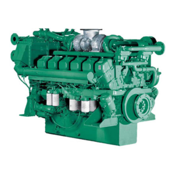
Presentation D34A MS The D34A MS is a direct injection, 12-cylinder, 4-stroke V-engine. It is equipped with two turbochargers and fitted with either a heat exchanger for thermostat-regulated freshwater cooling or connections for keel cooling. An optimal combination of combustion chambers, fuel injection system, effective turbocharger and charge air cooling, provide excellent fuel consumption over the whole range of speeds where the engine is economical in operation. -
Page 16: D34A Mt
Presentation D34A MT The D34A MT is a direct injection, 12-cylinder, 4-stroke V-engine. It is equipped with two turbochargers and fitted with either a heat exchanger for thermostat-regulated freshwater cooling or connections for keel cooling. An optimal combination of combustion chambers, fuel injection system, effective turbocharger and charge air coo- ling, provide excellent fuel consumption over the whole range of speeds where the engine is economical in opera- tion. -
Page 17: New Engine Initial Service
New engine initial service General Before starting a new or reconditioned engine for the first time, give it an initial inspection. This to guarantee your own safety as well as the maximum service life of the engine. External inspection Electrical wiring 1. -
Page 18: Starting
Starting Before starting WARNING! Before starting the engine make sure that neither people, nor tools, are in contact with moving parts of the engine. Notify the people in the vicinity of the engine when starting it. WARNING! Make sure that you know how to stop the engine before you start it (in case of emergency). If you are starting the engine for the first time, have someone stand-by at the emergency stop lever to stop the engine in case abnormal noise occurs during start up. -
Page 19: Non-Classifiable Control System
Non-classifiable control system This chapter describes the non-classifiable control system which is available for your engine. Note that that tacho- meter, oil gauge, temperature gauge, charge gauge, starting switch, etc., that are shown here as panel mounted, in some cases may be mounted separately. If the vessel is equipped with instruments not described here and you are not sure of their function, please get in touch with the shipyard or the company that installed the installation aboard the vessel. - Page 20 Standard Control System Warning displays If the acoustic alarm sounds, one of the warning dis- play lamps will immediately start to flash to indicate the cause of the alarm. 1. High coolant temperature. 2. Low lubricant pressure. 3. Generator not charging After an alarm Press the “Alarm test”...
-
Page 21: Starting Procedure
Standard Control System Starting procedure 1. Disengage the reverse gear and make sure the turning gear is not engaged. Put the control lever into neutral and idle on all control positions WARNING! If the vessel is equipped with controls that allow starting the engine in gear, it is essential to check all control positions to make sure a gear is not engaged. -
Page 22: Operation
Standard Control System Operation Learn how to handle the engine, controls and other equip- ment in a safe and correct manner before taking it into ope- ration. Checking the instruments Check the instruments and warning display directly after start and regularly during operation. Oil pressure During operation, the oil pressure gauge should show a rea- ding of 0,50 - 0,64 MPa (71 - 93 psi). -
Page 23: Stopping The Engine
Standard Control System Alarms and fault indication If the acoustic alarm sounds, one of the warning dis- play lamps will immediately start to flash to indicate the cause of the alarm: High coolant temperature (1), low oil pressure (2) and no charge voltage (3). IMPORTANT! Stop the engine immediately after an alarm for low oil pressure. -
Page 24: Operation
Operation General Learn how to handle the engine, controls and other equipment in a safe and correct manner before starting the engine WARNING! Stay clear of all rotating and moving WARNING! At operating temperature, the engine parts during operation. and its components are hot. A hot engine always involves risk for burn injuries. - Page 25 Operation Applying load Manoeuvring When the engine has reached operation temperature, The marine gear must be engaged at low idling speed. bring the engine to operating speed and apply the load There must be a brief pause after engaging gear befo- gradually.
- Page 26 Operation Manual speed control Manual speed adjustment of the engine can be done using the manual speed control knob. 1. Disconnect the control cable connected to the remote speed adjustment. 2. Turn the Lock counterclockwise to unlock the ma- nual speed adjustment knob. 3.
- Page 27 Operation 4. Fine-tuning of the engine speed can be done by turning the control knob: Turn the knob clockwise to decrease engine speed. Turn it counterclockwise to increase engine speed. 5. Bring the manual speed control knob in the neutral position when ready with the manual speed adjustment.
- Page 28 Operation Start using auxiliary batteries WARNING! Ventilate well. Batteries generate oxyhydrogen gas, which is extremely flammable and explosive. A short circuit, naked flame or spark can cause a powerful explosion. Never reverse the polarity of the battery. Risk of sparks and explosion. 1.
-
Page 29: Stopping
Stopping Allow the engine to run at low idling speed (in neutral) for at least 5 to 6 minutes before turning it off. This will keep the engine temperature in balance and prevent it from boiling. IMPORTANT! The procedure described above IMPORTANT! If the engine stops abnormally, is especially important if the engine has been try to locate the problem and make the... -
Page 30: Anti-Freezing Measures
Stopping the engine Anti-freezing measures If the engine room cannot be protected from frost, the rawwater system must be drained (if it contains raw- water) and the coolant in the freshwater system must contain the right mix of anti-freeze and water. Refer to chapter Maintenance “Rawwater system”... -
Page 31: Maintenance
Volvo Penta recommends that accurate maintenance records are kept. With accurate maintenance records your Volvo Penta Dealer can help in fine tuning the recommended service intervals to meet the specific operating situ- ation. This should result in a lower engine operation cost. -
Page 32: Maintenance Schedule
Maintenance schedule D34A MS Daily before first start General inspection engine and engine room Check and make sure all valves are in the right position Check lubrication oil level Check marine gear oil level Check coolant level Drain water from fuel tank... - Page 33 Maintenance schedule Every 250 operating hours or every 12 months Change lubrication oil. Longer interval requires oil analysis Change full flow and by-pass lubrication oil filters Check/adjust V-belts Check rawwater filter Check/wash air inlet silencer filter Every 500 operating hours or every 12 months Change governor lubrication oil filter Clean centrifugal by-pass lubrication oil filter Every 1000 operating hours or every 12 months...
- Page 34 Maintenance schedule Every 4000 to 6000 operating hours or every 24 months Full service inspection Every 12 months Check rubber engine mounts Check rubber hoses and flex connections Check engine room ventilation fans Every 10000 operating hours Check torsional vibration damper temp check Check rubber of flexible coupling for deformation and cracks Replace ball-joints in fuel pump control linkage Check all safety switches, instruments and senders...
- Page 35 Maintenance schedule D34A MT Daily before first start General inspection engine and engine room Check and make sure all valves are in the right position Check lubrication oil level Check marine gear oil level Check coolant level Drain water from fuel tank Drain water from fuel pre-filter/water separator Drain water from air vessel and air filter Check engine control system (cables, etc.)
- Page 36 Maintenance schedule Every 250 operating hours or every 12 months Change lubrication oil. Longer interval requires oil analysis Change full flow and by-pass lubrication oil filters Check/adjust V-belts Check rawwater filter Check/wash air inlet silencer filter Every 500 operating hours or every 12 months Change governor lubrication oil filter Clean centrifugal by-pass lubrication oil filter Every 1000 operating hours or every 12 months...
- Page 37 Maintenance schedule Every 4000 to 6000 operating hours or every 24 months Full service inspection Every 12 months Check rubber engine mounts Check rubber hoses and flex connections Check engine room ventilation fans Every 10000 operating hours Check torsional vibration damper temp check Check rubber of flexible coupling for deformation and cracks Replace ball-joints in fuel pump control linkage Check all instruments, senders and switches...
-
Page 38: Overhaul Information
Maintenance schedule Overhaul information Top overhaul Dependent of your application, working conditions and service level a “top overhaul” might be required in case of: Gas leakage through valves Too much valve clearance Low compression pressure Top overhaul includes: Remove cylinder heads and check liners and com- Change freshwater pump seals bustion chambers of pistons Change rawwater pump seals... - Page 39 Maintenance schedule major overhaul Disassemble engine, clean, check and change major parts. Major parts: Inlet and exhaust valve seats Cylinder liners Inlet and exhaust valves Main bearing cap bolts and washers Valve rotators Piston rings Valve cotters Connecting rod bearings Rocker arm adjusting screws Vibration damper Valve push rods...
-
Page 40: Recommendation Of Daily Operation Records
Maintenance: General Recommendation of Daily Operation Records Daily recording is a preventive maintenance program and when comparing values with engine history it will help you recognize conditions, signs or indications of approaching trouble. Daily operation records also make trouble shooting easier and will lessen the down time (to save time and money for servicing). Items to be recorded The following items are recommended to be recorded once a day:... -
Page 41: Engine
Maintenance: Engine Engine Valve clearance Check and adjust the valve clearance on a cold engine. The valves are adjusted when the piston is at top dead center of compression stroke. The valve bridge is adjusted first, and then the clearance of the rocker arm. IMPORTANT! The engine must under no circumstances be running when checking and adjusting the valve clearance since the valves can knock against the pistons and cause serious damage. - Page 42 Maintenance: Engine Valve clearance inspection 1. Check the valve clearance with feeler gauges in- serted between the rocker arm and yoke cap. Valve Clearance: Inlet valve ........0.4 mm [ 0.016 in.] Exhaust valve ......0.5 mm [ 0.020 in.] 2.
-
Page 43: Turning The Engine
Maintenance: Engine Turning the engine Insert the turning bar in the holes on the flywheel. Turn the engine manually. Warning! Make sure the turning bar is removed before cranking the engine. Vibration damper inspection NOTE! When installing a damper protective cover on the engine, do not use a cover enclosing the damper. -
Page 44: Lubrication System
Maintenance: Lubrication system Lubrication system Checking oil level The oil level must be within the marked range on the dipstick and must be checked daily. IMPORTANT! The level must never be allowed to drop beneath the minimum or rise above the maximum mark on the dipstick. -
Page 45: Changing Oil
Maintenance: Lubrication system Changing oil Always observe the recommended oil change interval. IMPORTANT! Only use recommended grades of oil (see chapter technical data). 1. Warm up the engine (this makes it easier to suck the oil up from the sump). Then stop the engine. WARNING! Hot oil and hot surfaces may cause burns. -
Page 46: Changing Oil Filter
Maintenance: Lubrication system Changing oil filter Each pair of filters has its own shut off valve located on the housing between the filters. The oil filters can be changed while the engine is running as the oil flow can be directed through two filters at a time. WARNING! Always keep all four filters in operation under norlmal operating conditions. -
Page 47: Cleaning Centrifugal By-Pass Oil Filter
Maintenance: Lubrication system Cleaning centrifugal by-pass oil filter Remove the cover and clean inside with clean diesel. NOTE! In case by-pass filter is very dirty, shorten check interval, refer to chapter ”Maintenance schedu- le”. Changing hydraulic governor oil filter 1. Stop the engine. 2. -
Page 48: Fuel System
Maintenance: Fuel System Fuel system WARNING! Always protect your hands when carrying out leak detection. Escaping fluids under pressure can pierce bodily tissue and cause serious injury. Risk of blood poisoning. Always cover any electric component if it is located under the fuel filter. Otherwise it might be damaged by fuel spills. WARNING! Work performed on the fuel system must be done on a cold engine. - Page 49 Maintenance: Fuel System Bleeding the fuel injection pumps 1. Loosen the air vent cock on the fuel injection pump about 1.5 turns. 2. Move the priming pump cap up and down to start the flow of fuel through the system. 3.
-
Page 50: Changing The Fuel Filter
Maintenance: Fuel System Changing the fuel filter Switchable fuel filters can be changed while the engi- ne is running as the flow of fuel can be cut off to one filter at a time. WARNING! Working on or approaching a running engine is a safety hazard. -
Page 51: Changing The Fuel Injector Nozzle
Maintenance: Fuel System Changing the fuel injector nozzle IMPORTANT! Cover all open fuel injection pipes, fuel intake openings and the fuel injection nozzle to keep dirt out Removing the fuel injector 1. Remove the rocker cover. 2. Remove the clamp from the fuel injection pipe. 3. -
Page 52: Fuel Injection Pressure
Maintenance: Fuel System Installing the nozzle 1. Install the nozzle according to the pin on the nozzle. 2. Tighten the retaining nut by applying the specified torque 177 to 196 Nm (18 to 20kpm) [130 to 145 lbf.ft]. (Apply oil to the nut.) IMPORTANT! Do not use Moly Disulfide. - Page 53 Maintenance: Fuel System Fuel injection nozzle spray pattern Check spray conditions when checking fuel injection pressure. Good spray conditions are as follows: · Fuel is injected from all nozzle holes. · The fuel is sprayed in a conical shape. · No big particles but fine ones.
-
Page 54: Injection Timing Inspection
Maintenance: Fuel System Injection timing inspection The injection timing is indicated on the caution plate attached to the No. 1 rocker cover. Check it before inspection. Bring the piston for No. 1 cylinder to top dead center on compression stroke as follows: 1. -
Page 55: Checking Fuel Control
Maintenance: Fuel System Adjusting fuel injection timing 1. Make sure the timing mark (indicated on the cau- tion plate) is aligned with the pointer, with the pis- ton for the cylinder at top dead center on com- pression stroke. 2. Loosen the bolts(3) for the fuel injection pump coupling. -
Page 56: Twin Fuel Pre-Filter/Water Separator
Maintenance: Fuel System Twin fuel pre-filter/water separator WARNING! Working on or approaching a running engine is a safety hazard. Beware of rotating parts and hot surfaces. The dual filter is equipped with a pressure gauge (1) indicating when it is time to change the filter insert. The filter inserts must be changed according to the maintenance schedule recommendations or earlier if the pressure gauge indicates a vacuum of 6–10 inHg... - Page 57 Maintenance: Fuel System 1. Place a drip pan under the filter. 2. Undo the T-bolt (2) and remove the cover (3). 3. Take out the insert carefully while turning it. 4. Drain off water and contaminants through the drain plug (4). 5.
-
Page 58: Air Inlet And Exhaust Systems
Maintenance: Air inlet and exhaust system Air inlet and exhaust systems Turbocharger inspection WARNING! Check the turbocharger only when the engine is cool and the compressor wheel is not rotating. Check shaft play, take a hold of the compressor wheel nut and turn the wheel to feel rattle and listen for abnormal noise. -
Page 59: Washing The Air Inlet Silencer Filter
Maintenance: Air Inlet and exhaust system Washing the air inlet silencer filter Remove dust from the air filters on the suction side of the turbocharger silencers . Be sure to keep the air filters clean to ensure optimum engine performance. 1. -
Page 60: Cooling System, General
Maintenance: Cooling system, general Cooling system, general The freshwater system is the internal cooling system of the engine. It is a closed system and shall always be fil- led with coolant that protects the engine from internal corrosion and frost damage if the climate requires it. Anti- corrosive additives become less efficient with age and the coolant must therefore be changed in accordance with the recommendations in the maintenance schedule. -
Page 61: Cooling System D34A Ms He
Maintenance: Cooling system, general Cooling system D34A MS HE The thermostat regulated freshwater system is cooling the lubrication oil coolers, the engine and the charge air coolers. An engine driven cooling water pump circulates the coolant through the heat exchanger and through the engine. -
Page 62: Cooling System D34A Ms Kc
Maintenance: Cooling system, general Cooling system D34A MS KC The engine cooling water is cooled by, e.g, a box cooler, a grid cooler, or any other external heat exchanger. The same coolant (fresh water) is cooling the complete engine. 1. Freshwater inlet 2. -
Page 63: Cooling System D34A Mt He
Maintenance: Cooling system, general Cooling system D34A MT HE The thermostat regulated freshwater system is cooling the engine and the lubrication oil cooler. An engine driven cooling water pump circulates the coolant through the heat exchanger and through the engine. The rawwater system is cooling the charge air and the coolant in the freshwater cooling system. -
Page 64: Cooling System D34A Mt Kc
Maintenance: Cooling system, general Cooling system D34A MT KC The thermostat regulated freshwater system is cooling the engine and the lubrication oil cooler. The engine coo- ling water is cooled by, e.g, a box cooler, a grid cooler, or any other external heat exchanger. The rawwater system is cooling the charge air. -
Page 65: Freshwater System
Maintenance: Freshwater system Freshwater system Checking the coolant level MS engines Make sure the level is between the MIN and MAX marks. If there are no marks, the coolant level should be approximately 5 cm below the top of the filler cap. For coolant specification, refer to chapter “technical data”... -
Page 66: Draining The Coolant
Maintenance: Freshwater system 5. Close air vents. Check the coolant level and top up if needed. IMPORTANT! Make sure that the engine is filled with lubrication oil before starting or cranking the engine. IMPORTANT! The engine must not be started before the system has been bled and topped up. -
Page 67: Rawwater System
Maintenance: Rawwater system Rawwater system The rawwater system is the engine’s external cooling system. It cools the internal cooling system in an engine mounted or externally mounted heat exchanger. The system is protected against galvanic corrosion by zinc ano- des located in the heat exchanger. Keep the engine room heated or use an antifreeze coolant in the rawwater system. -
Page 68: Checking/Changing Rawwater Pump Impeller
Maintenance: Rawwater system Checking/Changing rawwater pump impeller IMPORTANT! Always keep a spare impeller and gasket in store aboard the ship. 1. Drain the external cooling water as described in the chapter draining the rawwater system. 2. Remove the pump end cover. Remove the impell- er using a puller, remember direction of rotation. -
Page 69: Electrical System
Maintenance: Electrical system Electrical system Protective devices inspection Make sure that the instruments and the alarm func- tions of the engine control system work properly. Checking the electrical wiring Check for loose or damaged electrical cables. Damaged cables must be replaced. Starter motor inspection 1. -
Page 70: Inhibiting
Before taking the engine out of service for long periods, it should be checked by a Volvo Penta dealer for possible needed overhaul or repaire of the engine and other equip- ment. - Page 71 Inhibiting Storage of engine in operating condition Service the engine once a month in the following manner: 1. Crank the engine two times, for 10 seconds each time, with the starter at intervals of 30 seconds, with the fuel supply shut off. 2.
-
Page 72: Troubleshooting
A number of symptoms and possible causes for engine disturbances are described in the table below. If faults or hitches arise that you cannot solve alone, you must always get in touch with your Volvo Penta dealer. NOTE! Dust and foreign particles are the most common cause of excessive wear of parts. When disassembling a component, take measures to prevent dust and foreign particles from entering it. -
Page 73: Technical Data
Technical Data D34A MS General Number of cylinders ..........Displacement ............33,93 liters (2071 in Nominal idling speed ..........not available Low idling speed ............ 625 ±25 rpm High idling speed ........... 2006 rpm [rating 1] 2150 rpm [rating 2] Valve clearance* ........... -
Page 74: D34A Mt
Technical Data D34A MT General Number of cylinders ..........Displacement ............33,93 liters (2071 in Nominal idling speed ..........not available Low idling speed ............ 625 ±25 rpm High idling speed ........... 2006 rpm [rating 1] 2150 rpm [rating 2] Valve clearance* ........... -
Page 75: Fuel Specification
Technical Data Fuel specification Fuel must comply with national and international standards at the least, e.g.: JIS KK 2204....... Type1, Type2, Type3 ASTM, D975 ........No.1-D, No.2-D BS2869 ........Class-A1, Class-A2 DIN51601 ..........Diesel-Fuel ISO8217 ..........DMX-Class Note! It is necessary to use a fuel that has a pour point suitable for ambient temperature during the operation of the engine. -
Page 76: Lubrication Oil Specification
Technical Data Lubrication oil specification Recommended types of engine oil Use lubrication oil that meets Class CF standard (recommended engine oil). Class CE and CF-4 engine oils are designed for diesel fuel with a sulfur content of less than 0,5% and less than 0,2%, respectively. Since the sulfur content of most Class-A diesel fuel exceeds 0,5%, do not use class CE or CF-4 engine oil when using class-A diesel fuel Important! Use of improper or inferior oil can cause excessive wear of bearings and moving parts,... -
Page 77: Coolant Specification
The mixture of Volvo Penta Coolant and water should contain 40-55% Volvo Penta Coolant. If the coolant con- tains less than 40% Volvo Penta Coolant, the cooling galleries in the engine or radiator may be blocked by con- tamination. If the coolant contains more than 60% Volvo Penta Coolant the cooling ability of the coolant mixture is impaired, this may cause the engine to overheat. -
Page 78: Tightening Torque Table
Technical Data Tightening torque table Important bolts and nuts D34 MS Thread Torque Description Diam.xPitch lbf.ft Notes (M-Thread) Cylinder head bolts 20 x 2,5 (a) (b) (c) Rocker shaft brackets 12 x 1,75 Rocker arm lock nuts 12 x 1,25 Valve bridge lock nuts 10 x 1,25 Camshaft gear... - Page 79 Technical Data Important bolts and nuts D34 MS Thread Torque Description Diam.xPitch lbf.ft Notes (M-Thread) Fuel rack control lever 8 x 1,25 Injection pump drive gear 30 x 1,5 Injection pump laminate plate 12 x 1,75 83-93 8,5-9,5 61-69 Injection pump coupling shaft 14 x 1,5 83-93 8,5-9,5...
- Page 80 Technical Data Important bolts and nuts D34 MT Thread Torque Description Diam.xPitch lbf.ft Notes (M-Thread) Cylinder head bolts 20 x 2,5 (a) (b) (c) Rocker shaft brackets 12 x 1,75 Rocker arm lock nuts 12 x 1,25 Valve bridge lock nuts 10 x 1,25 Camshaft gear 30 x 1,5...
- Page 81 Technical Data Important bolts and nuts D34 MT Thread Torque Description Diam.xPitch lbf.ft Notes (M-Thread) Rawwater pump cam (screw) 10 x 1,25 14-16 1,4-1,6 10-12 Rawwater pump casing 8 x 1,25 0,7-0,8 Rawwater pump cover 8 x 1,25 0,7-0,8 Rawwater pump pulley (nut) 33 x 3,5 Fuel rack control lever 8 x 1,25...
- Page 82 Technical Data Standard bolts and nuts Fine threads Thread Strength classification diameter x pitch 10.9 mm [in.] lbf.ft lbf.ft M10 x 1,25 [0.39 x 0.049] M12 x 1,25 [0.47 x 0.049] 11,0 M14 x 1,5 [0.55 x 0.059] 17,9 M16 x 1,5 [0.63 x 0.059] 14,8 26,7 M18 x 1,5 [0.71 x 0.059]...
- Page 83 Technical Data Standard union nuts Cap nut size Strength classification Nominal diameter x pitch diameter mm [in.] lbf.ft M14 x 1,5 [0.55 x 0.059] M16 x 1,5 [0.63 x 0.059] M20 x 1,5 [0.79 x 0.059] M22 x 1,5 [0.87 x 0.059] M27 x 1,5 [1.06 x 0.059] M30 x 1,5 [1.18 x 0.059] M30 x 1,5 [1.18 x 0.059]...
-
Page 84: Identification Numbers
Technical Data Identification numbers Type plates with identification numbers can be found on the engine and the transmission or generator. This infor- mation must always be used as a reference when ordering service and spare parts. Engine ............................Product designation ........................Serial and basic engine number .................... -
Page 85: Sea Trial Data
Sea trial data Date ................. Name ............... Vessel ..............Engine no..............Miscellaneuos Engine speed ..............................rpm Vessel speed ..............................knots Ambient/eng. room temp..........................Sea water temp..............................Eng. cooling water out Left bank ........................Eng. cooling water out Right bank ........................Cooler in ................................ -
Page 86: Notes
Notes ........................................................................................................................................................................................................................................................................................................................................................................................................................................................................................................................................................................................................................................................................................................................................................................................................................................................Plus d'informations sur : www.dbmoteurs.fr... - Page 87 ........................................................................................................................................................................................................................................................................................................................................................................................................................................................................................................................................................................................................................................................................................................................................................................................................................................................................................................................................................................Plus d'informations sur : www.dbmoteurs.fr...
- Page 88 ............................................................................................................................................................................................................................................................................................................................................................................................................................................................................................................................................................................................................................................................................................................................................................................................................................................................................................. Plus d'informations sur : www.dbmoteurs.fr...
- Page 89 Plus d'informations sur : www.dbmoteurs.fr...
Need help?
Do you have a question about the D34A MS and is the answer not in the manual?
Questions and answers