Advertisement
Quick Links
KOLVER S.r.l. declares that the new tool here described: control unit model EDU2AE/TOP/TA is in conformity
with the following standards and other normative documents:
2006/42/CE, LVD 2014/35/UE, EMCD 2014/30/UE, EN 62841-2-2:2014, EN 62841-1: 2015, EN 60204-1,
EN 61000-6-2, EN 61000-6-4.
It is also in conformity with RoHS III normative (2011/65/UE and following 2015/863).
Name:
Position:
Thiene, January 1
st
2022
MANUAL
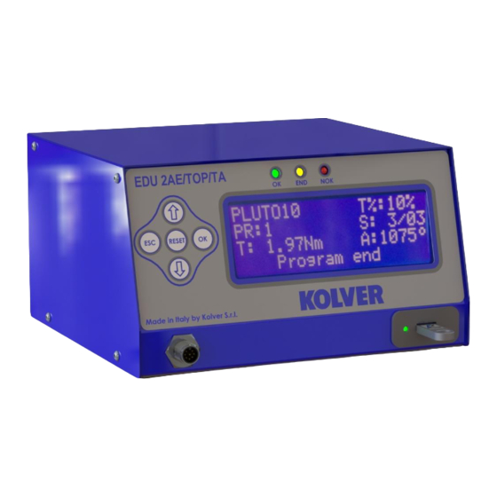
EDU 2AE/TOP/TA
Torque range: 0.35-70 Nm
IDENTIFICATION DATA OF THE MANUFACTURER
U
VIA M. CORNER, 19/21
36016 THIENE (VI) ITALIA
IDENTIFICATION DATA OF THE PRODUCT
U
MODEL:
CODE:
TECHNICAL DATA OF THE PRODUCT
DIMENSIONS: 190 x 205 x h120 mm WEIGHT: 2,5 Kg
DECLARATION OF CONFORMITY
Giovanni Colasante
General Manager
Person authorized to compile the technical file in Kolver
KOLVER S.r.l.
EDU2AE/TOP/TA
034000/TOP/TA
FUSE: 3,15 A
Giovanni Colasante
Advertisement

Related Manuals for Kolver EDU 2AE/TOP/TA


Summary of Contents for Kolver EDU 2AE/TOP/TA
- Page 1 DIMENSIONS: 190 x 205 x h120 mm WEIGHT: 2,5 Kg DECLARATION OF CONFORMITY KOLVER S.r.l. declares that the new tool here described: control unit model EDU2AE/TOP/TA is in conformity with the following standards and other normative documents: 2006/42/CE, LVD 2014/35/UE, EMCD 2014/30/UE, EN 62841-2-2:2014, EN 62841-1: 2015, EN 60204-1, EN 61000-6-2, EN 61000-6-4.
- Page 2 Read the menu description carefully and in case you are unsure please contact Kolver for support information. Turn the unit on through the on/off switch on the back panel. The unit will carry a general system check and the words “waiting connection”...
- Page 3 K o l v e r S . r . l . E D U 2 A E / T O P / T A V e r s i o n 6 . 0 0 l o a d i n g . . . When turned on and the screwdriver is connected, the unit is set to % mode and the display will contain the following information: P L U T O 1 0...
-
Page 4: Program Menu
MAIN MENU: - - - - - M A I N - M E N U - - - - - - c h a n g e E S C q u i t P r o g r a m s e t t i n g ... - Page 5 - - - - - M E N U - - P R : 1 - - - - - 3 ) M o d e l : P L U T O 1 0 4 ) R a m p : 0 .
- Page 6 ATTENTION: the torque target value added to the compensation must in any case be contained in the torque range relating to the set speed. Any invalid value will be signaled with "Torque/ speed error". 7) Tm Fast Spd (Time Fast Speed): It indicates how long the screwdriver should turn at the FAST SPEED (see point 7) before switching to the Final Speed.
- Page 7 12) Max time - Maximum time: You can select the maximum time of screwing. You can set from 'Min time + 0,1s' to 20.0 sec. You also can set the Maximum time to OFF by pressing the button when you have reached the value of 20.0s.
- Page 8 This function overlaps other time settings (Fast Speed, ramp time, minimum time, maximum time) from the motor start on. ATTENTION: This function is useful for applications where the prevailing torque is higher than the final torque (for example trilobal screws or locknuts). Please use this function with utmost attention because an incorrect use can damage both the assembly and the screwdriver.
- Page 9 25) Torq min – Minimum torque: The minimum torque and maximum torque options allow the user to set the acceptable torque range for each single application. When the reached torque is within this range, “Screw OK” will be displayed on the status bar and the green led will light up. If the reached torque is outside this range, “error minimum torque”...
-
Page 10: Sequence Menu
- - - - - M E N U - - P R : 1 - - - - - 3 1 ) A n g . m i n : - - - - 3 2 ) A n g . m a x : - - - - ... -
Page 11: Option Menu
5) Ins. Barcode Seq: When ON on “Barc. Mode → ON Seq.”, you have to scan the barcode to enable the Sequence. IMPORTANT: Barcode can be ONLY numeric. - - - S E Q U E N C E - M E N U - - - - 6 ) R e s e t S e q . - Page 12 When EXT, functions can only be enabled through proper connections on the back panel (see paragraph I/O connections). When INT+EXT you can press either the button on the front or on the back panel. 5) Unit: You can choose between the following units of measurements: Nm, lbf.in and kgf.cm. - - - - O P T I O N S - M E N U - - - - 6 ) T o r q u e s e t :...
-
Page 13: Usb Options
- - - - O P T I O N S - M E N U - - - - 9 ) S e t t i m e & d a t e 1 0 ) C y c l e s : 0 0 0 0 0 0 0 ... - Page 14 TORQUE CALIBRATION (only % mode) The torque calibration function allows to view the torque value in Nm or in.lbs or kgf.cm directly on the display of the control unit. IMPORTANT: You need a torque tester to proceed, either with static transducer (model minik or K) or with rotary transducer (model minik-e).
- Page 15 In case of error, you will see: - - - - - - - - S T E P - - 1 - - - - - S t a r t t e s t E r r . R e p e a t S c r e w i n g Just repeat the test.
- Page 16 USE OF T&A (Torque & Angle) Choose the T & A mode (see point 29: Modify function on the program menu) It is possible to set 6 different modes: TORQUE (Torque): It’s the most common use mode. The control unit shows the tightening torque and the torque starting from a certain torque percentage (threshold torque, see point 30).
- Page 17 TORQUE/LEVER (T/LV): No threshold is preset by the operator: the angle value that appears on the display corresponds to the angle that is carried out starting from the moment in which the lever is pressed until the torque is reached. ...
- Page 18 ANGLE/LEVER (A/LV): the threshold torque value can’t be set by the operator and the angle value that appears on the display corresponds to the angle that is carried out starting from the moment in which the lever is pressed. The angle has to be set in the "Ang. max ". If the lever is released before reaching the set angle, the error "Error ang not OK"...
- Page 19 PLUTO 10 Lbf.in Kgf.cm 15,0 17,3 32,7 10,2 37,7 40,7 10,2 46,9 46,0 11,3 53,0 10,7 56,6 12,3 65,3 11,6 64,6 13,3 74,4 13,3 69,9 15,3 80,6 13,3 80,5 15,3 92,8 PLUTO 15 Lbf.in Kgf.cm 11,6 22,1 13,3 25,5 13,3 39,8 15,3 45,9...
- Page 20 PLUTO 35 Lbf.in Kgf.cm 22,2 79,7 25,5 91,8 13,3 39,0 117,7 44,9 135,6 16,6 43,4 146,9 50,0 169,3 19,0 47,0 168,2 54,1 193,7 21,9 50,5 193,8 58,2 223,3 25,0 55,8 221,3 64,3 254,9 28,9 59,3 255,8 68,4 294,7 30,6 61,1 270,8 70,4 312,0...
- Page 21 PLUTO 6 ANG Lbf.in Kgf.cm 17,7 20,4 27,4 10,2 31,6 35,4 11,3 40,8 10,7 40,7 12,3 46,9 11,6 45,1 13,3 52,0 12,4 48,7 14,3 56,1 13,3 52,2 15,3 60,2 15,1 54,0 17,4 62,2 PLUTO 8 ANG Lbf.in Kgf.cm 15,0 10,2 17,3 10,7 31,0...
- Page 22 INTERPRETATION OF ACOUSTIC SIGNALS The control unit emits sounds which help you understand if the screwing has been carried out correctly or not. When the torque is reached meeting all the parameters set, the control unit utters a 0.5 sec beep as confirmation.
- Page 23 to protection, displaying the message "output disable". To restore the outputs after a protection, turn off and turn on the unit again. Vers. 100822 Page 23...
- Page 24 • CN1 CONNECTOR – 10 pins It is situated on the upper part of the back panel. NAME FUNCTION OUTPUT +24V voltage protected. The maximum current consumption is 400mA. CAN NOT BE +24V USED TO POWER EXTERNAL DEVICES. Common pin. Signals must be taken between this pin (GND and the respective signal pins (pin 3, 4 and 5).
- Page 25 • CN2 CONNECTOR – 14 pins All of the following pins are input: make a contact with pin 14 to activate them. NAME FUNCTION Remote motor stop. If it’s activated the message “STOP MOTOR ON” appears STOP MOTOR on the display. The motor will stop and won’t start working again as long as the contact is closed (as Input pin 1 of CN2).
- Page 26 • CN3 CONNECTOR – 11 pins All of the following pins are output. NAME FUNCTION This signal works in parallel with the green led on the front panel. GREEN LED This signal works in parallel with the red led on the front panel. RED LED This signal works in parallel with the yellow led on the front panel.
- Page 27 • CN4 CONNECTOR – 9 pins All of the following pins are output. NAME FUNCTION It indicates you’re using program 1 OUTPUT 1 It indicates you’re using program 2 OUTPUT 2 It indicates you’re using program 3 OUTPUT 3 It indicates you’re using program 4 OUTPUT 4 It indicates you’re using program 5 OUTPUT 5...
- Page 28 • CN5 CONNECTOR (25 pin connector - female): NAME FUNCTION Common to every input. Signals have to be enabled making contact between the desired signal and this pin (common 0VDC). Not used It indicates stop motor is enabled STOP MOTOR OUT It indicates you’re using program 8 OUTPUT 8 It indicates you’re using program 7...
- Page 29 • CN7 CONNECTOR (9 pin serial connector - female) – PRINT FUNCTION NAME FUNCTION +15V Not used. Serial transmission. Serial reception. Common to every input. Signals have to be enabled making contact between the desired signal and this pin (GND). Not used.
-
Page 30: Troubleshooting
ERROR PROBLEM SOLUTION “waiting connection” doesn’t turn into “loading” after Contact the nearest Kolver dealer. it’s been switched on. “Error Torque Control” is displayed on the status bar Make a new screw. If the error persists, change the torque and speed settings. - Page 31 - Unscrewing too heavy A for at least 500 ms) ATTENTION: IF THE OK/ESC OPTION IS DISABLED, ERRORS RESET AT THE FOLLOWING SCREW/PROGRAM. OTHERWISE PRESS ESC. IF THE PROBLEM PERSISTS, PLEASE CONTACT YOUR NEAREST KOLVER DEALER. Vers. 100822 Page 31...
- Page 32 PIN 5 = GND) and a mini USB connector. You can print the results of each screwing on a printer (for example Kolver model PRNTR1) and/or on PC (for example through Hyper Terminal or Realterm or any data transmission program or EDU EXPAND). You can also save those results on a USB device. The transmission characteristics (only serial and USB) are the following: 9600 (bits per second), 8 (data bits), n (no parity), 1 (bits stop 1).
- Page 33 EDU EXPAND is the software for pc created by Kolver to set, change and save all parameters of EDU2AE/TOP/TA unit. It communicates with the control unit via miniUSB or RS232 and makes you create up to 100 different settings configurations, save them on your USB drive and then recall on your EDU unit.
- Page 34 To modify or enter any parameter values, double click a cell, select a number within the proper range, then press Enter. If the value is not within its valid range, pressing Enter will not confirm the change. Save to file: it saves all programs to a file. This file can be read directly from a USB drive connected to the unit on its front panel.
- Page 35 Report of the screwing done If you connect the USB drive to the control unit, the unit creates a folder where the report of the screwing done will be saved. The folder is named as the serial number of the unit. The text file which contains all the screwing data is named as the current date.
- Page 36 EXPLODED VIEW: EDU2AE/TOP/TA 6.00 Vers. 100822 Page 36...
-
Page 37: Spare Parts
3x5 Button head screw burnished TX10 872444 Motor board 852521/SW M3 toothed washer 800041 Switching 48V 600W 872490 M3 burnished nut 800056 I/O EDU 2AE/TOP/TA board 852525/TA M3 brass nut 800056/O Ground cable 800090/E Ferrite 872468 Display board EDU2AE/TOP 852526... - Page 38 7. No one, whether an agent, servant or employee of KOLVER, is authorized to add to or modify the terms of this limited guarantee in any way. However it’s possible to extend the warranty with an extra cost.
Need help?
Do you have a question about the EDU 2AE/TOP/TA and is the answer not in the manual?
Questions and answers