Table of Contents
Advertisement
Quick Links
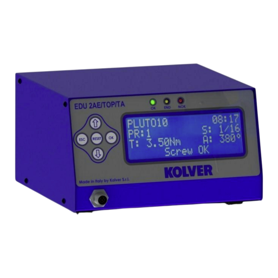
EDU 2AE/TOP e EDU 2AE/TOP/TA
TRANSFORMER: 230V or 110V AC 50 Hz – 40 V DC 200 VA FUSE: 3,15 A
KOLVER S.r.l. declares that the new tool here described : control unit model EDU 2AE is in conformity with
the following standards and other normative documents : 2006/42/CE, 2006/95/CE, 2004/108/CE, EN 60745-1,
EN 60204-1, EN 61000-6-1, EN 61000-6-3.
It is also in conformity with the RoHS II normative.
Name:
Position:
Thiene, Oct. 25, 2013
MANUAL
Torque range: 0.2-50 Nm
I DENTIFICATION DATA OF THE MANUFACTURER
U
VIA M. CORNER, 19/21
36016 THIENE (VI) ITALIA
I DENTIFICATION DATA OF THE PRODUCT
U
CONTROL UNIT MODEL: EDU 2AE TOP - EDU 2AE TOP/TA
CODE: 031000/TOP - 031000/TOP/TA
TECHNICAL DATA OF THE PRODUCT
DIMENSIONS: 190 x 205 x h120 mm WEIGHT: 4 Kg
DECLARATION OF CONFORMITY
Giovanni Colasante
General Manager
Person authorized to compile the technical file in Kolver
KOLVER S.r.l.
Giovanni Colasante
Advertisement
Table of Contents

Related Manuals for Kolver EDU 2AE/TOP


Summary of Contents for Kolver EDU 2AE/TOP
- Page 1 DIMENSIONS: 190 x 205 x h120 mm WEIGHT: 4 Kg DECLARATION OF CONFORMITY KOLVER S.r.l. declares that the new tool here described : control unit model EDU 2AE is in conformity with the following standards and other normative documents : 2006/42/CE, 2006/95/CE, 2004/108/CE, EN 60745-1, EN 60204-1, EN 61000-6-1, EN 61000-6-3.
- Page 2 (only PLUTO). It’s also possible to use the following clutch models: PLUTO 3FR, PLUTO 5FR and PLUTO 7FR. EDU 2AE/TOP delivers all the advantages of precision torque control electric tools at a fraction of the price of transdurized tools. The state-of-the-art electronic control circuit cuts the power supply to the motor calculating the correct torque in response to 3 parameters;...
- Page 3 LEDS ON FRON PANEL GREEN LED VERDE: indication of Screw OK. YELLOW LED: indication of Programm End or Sequence End. RED LED: any indication of error. Manual EDU 2AE/TOP and EDU 2AE/TOP/TA Rev. 3 Page 3...
-
Page 4: Program Menu
It indicates the menu section where you can set date and time, the password and the language. PROGRAM MENU: The first 28 menu lines are available in both the EDU 2AE/TOP and EDU 2AE/TOP/TA models. Lines from 29 to 32 are only available in the TOP/TA model. - Page 5 You can select any speed value of the screwdriver between nominal (maximum speed given in the catalogue) and the minimum speed of every single screwdriver (see table with technical data). Manual EDU 2AE/TOP and EDU 2AE/TOP/TA Rev. 3 Page 5...
- Page 6 1 6 ) P V t o r q u e : o f f 1 7 ) R o t a t i o n : r i g h t Manual EDU 2AE/TOP and EDU 2AE/TOP/TA Rev. 3 Page 6...
- Page 7 When OFF, this function doesn’t work. 22) Defix allow: when OFF, the reverse is NOT enabled. 23) Calibration: When ON, you will see the torque value (Nm or in.lbs) on the main screen. Manual EDU 2AE/TOP and EDU 2AE/TOP/TA Rev. 3 Page 7...
- Page 8 (for example a mini-K or a K model). Let's say you notice that the torque displayed in the unit EDU 2AE/TOP is +0.2 Nm higher than the value indicated on the tester (which is the right one).
-
Page 9: Sequence Menu
4 ) M o d . b a r c : O F F 5 ) I n s . b a r c o d e S e q Manual EDU 2AE/TOP and EDU 2AE/TOP/TA Rev. 3 Page 9... -
Page 10: Option Menu
3 ) P a s s w o r d : 4 ) E S C - O K - R S T : e x t 5 ) U n i t : Manual EDU 2AE/TOP and EDU 2AE/TOP/TA Rev. 3 Page 10... -
Page 11: Torque Calibration
During the calibration it’s impossible to go back to the previous screen. Press ESC to stop calibration and then repeat the screwings. CALIBRATION PROCESS: 1. Select Calibration at point 17 of the menu and press OK. 2. The following screen will appear on the display: Manual EDU 2AE/TOP and EDU 2AE/TOP/TA Rev. 3 Page 11... - Page 12 If the torque and/or angle are outside the preset values, the screw will be considered as incorrectly tightened. In this case the red led will light up and the message “Error Max (Min) Angle” or “Error Max (Min) Torque” will be displayed. Manual EDU 2AE/TOP and EDU 2AE/TOP/TA Rev. 3 Page 12...
- Page 13 Therefore it’s very important to set a torque value (line 4) which is sufficiently higher than the threshold value (line 27), so that the set value is reached before the screwdriver stops because of the reached torque. Manual EDU 2AE/TOP and EDU 2AE/TOP/TA Rev. 3 Page 13...
- Page 14 In case of Program End, the unit will utter other two beeps. On the other hand, torque reached under min time, during the Ramp time or under the Brake time (see error signals on the display) will cause the control unit to utter three beep sounds. Manual EDU 2AE/TOP and EDU 2AE/TOP/TA Rev. 3 Page 14...
- Page 15 I/O CONNECTIONS: Manual EDU 2AE/TOP and EDU 2AE/TOP/TA Rev. 3 Page 15...
- Page 16 Common pin. The desired function is activated through a contact between this pin and one of the other pins (pin 6, 7, 8, 9). This pin is connected to 0VDC to the ground. Manual EDU 2AE/TOP and EDU 2AE/TOP/TA Rev. 3 Page 16...
- Page 17 Switch – selection of program 1 INPUT 1 Common to every input (1-13). Signals have to be enabled making contact between the desired signal and this pin (common 0VDC) . Manual EDU 2AE/TOP and EDU 2AE/TOP/TA Rev. 3 Page 17...
- Page 18 It activates when stop motor is enabled. STOP MOTOR NOT USED NOT USED Common to every output. Signals have to be enabled making contact COM0VDC between the desired signal and this pin (common 0VDC) . Manual EDU 2AE/TOP and EDU 2AE/TOP/TA Rev. 3 Page 18...
- Page 19 OUTPUT 7 It indicates you’re using program 8 OUTPUT 8 Common to every output. Signals have to be enabled making contact between the desired signal and this pin (common 0VDC) . Manual EDU 2AE/TOP and EDU 2AE/TOP/TA Rev. 3 Page 19...
- Page 20 COM +15V Serial reception. Serial transmission. Common to every input. Signals have to be enabled making contact between the desired signal and this pin (common 0VDC). Not used. Manual EDU 2AE/TOP and EDU 2AE/TOP/TA Rev. 3 Page 20...
-
Page 21: Troubleshooting
(torque is not reached and the screwing time is over the preset maximum time). “Error PV torque” is displayed on the status bar (the torque signal is displayed inside the set maximum time). Manual EDU 2AE/TOP and EDU 2AE/TOP/TA Rev. 3 Page 21... - Page 22 A for at least 500 ms) ATTENTION: IF THE OK/ESC OPTION IS DISABLED, ERRORS RESET AT THE FOLLOWING SCREW/PROGRAM. OTHERWISE PRESS ESC. IF THE PROBLEM PERSISTS, PLEASE CONTACT YOUR NEAREST KOLVER DEALER. Manual EDU 2AE/TOP and EDU 2AE/TOP/TA Rev. 3 Page 22...
- Page 23 J: Joint = type of preset joint (H= hard o S=soft). Screw: Number of screws = number of tightened screws/total number of screws. Seq: Sequence stage = it indicates the stage of the sequence. T: Torque = torque value. Manual EDU 2AE/TOP and EDU 2AE/TOP/TA Rev. 3 Page 23...
- Page 24 Notice = in case of program end, it prints “Program End”, in case of sequence end, it prints “Seq. end” or it indicates the type of error (see paragraph: trouble shooting). Manual EDU 2AE/TOP and EDU 2AE/TOP/TA Rev. 3 Page 24...
-
Page 25: Exploded View
EXPLODED VIEW Manual EDU 2AE/TOP and EDU 2AE/TOP/TA Rev. 3 Page 25... -
Page 26: Spare Parts
I/O connector 9 pin spacing 3,81 800164 I/O connector 11 pin spacing 3,81 800165 I/O connector 14 pin spacing 3,81 800166 I/O connector 10 pin spacing 3,81 800102 Filtered plug 800718 Board support 872442 Manual EDU 2AE/TOP and EDU 2AE/TOP/TA Rev. 3 Page 26... - Page 27 7. No one, whether an agent, servant or employee of KOLVER, is authorized to add to or modify the terms of this limited guarantee in any way. However it’s possible to extend the warranty with an extra cost.
Need help?
Do you have a question about the EDU 2AE/TOP and is the answer not in the manual?
Questions and answers