Table of Contents
Advertisement
Quick Links
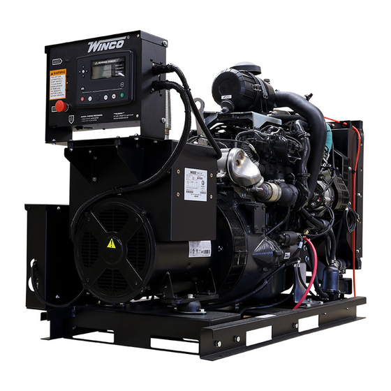
DE30F4-XX/4
GENERATOR
INSTALLATION AND
OPERATORS MANUAL
COPY YOUR MODEL AND SERIAL NUMBER HERE
No other WINCO generator has the same serial number as yours.
If you should ever need to contact us on this unit, it will help us to
respond to your needs faster.
MODEL __________________________________________________
SERIAL NUMBER _________________________________________
PURCHASE DATE _________________________________________
DEALER NAME ___________________________________________
DEALER PHONE # ________________________________________
www.wincogen.com
Advertisement
Table of Contents

Related Manuals for Winco DE30F4 4 Series


Summary of Contents for Winco DE30F4 4 Series
- Page 1 OPERATORS MANUAL COPY YOUR MODEL AND SERIAL NUMBER HERE No other WINCO generator has the same serial number as yours. If you should ever need to contact us on this unit, it will help us to respond to your needs faster.
-
Page 2: Table Of Contents
Should you experience a problem please follow the “Troubleshooting Tables” near the end of this manual. REPLACING BLOW-BY FILTER The warranty listed in the manual describes what you can STORAGE expect from WINCO should you need service assistance in MAINTENANCE SCHEDULE the future. TROUBLE SHOOTING TABLES OPM-158/B... -
Page 3: Safety Information
SAFETY INFORMATION C. Do not smoke or use open flame near the generator SAVE THESE INSTRUCTIONS set or fuel tank. D. Keep a fire extinguisher nearby and know its proper This engine generator set has been designed and use. Fire extinguishers rated ABC by NFPA are manufactured to allow safe, reliable performance. -
Page 4: Specifications
SPECIFICATIONS DE30F4 STANDBY PRIME VOLTS WATTS AMPS WATTS AMPS 120/240 1-PH 30,000 30.0 30,000 30.0 120/208 3-PH 30,000 37.5 30,000 37.5 120/240 3-PH 30,000 37.5 30,000 37.5 277/480 3-PH 30,000 37.5 30,000 37.5 346/600 3-PH 30,000 37.5 30,000 37.5 GENERATOR RESISTANCE (all value at 22°C) Model Stamford S1L2-K1... -
Page 5: Introduction
Go to the WINCO website for a list of engine dealers temperature, altitude, fuel, and other conditions specified (wincogen.com) or contact the WINCO Service Department. -
Page 6: Preparing The Unit
This must be completed and NOT PLACE FUEL IN THE TANK PRIOR TO LIFTING. returned to WINCO Inc. within 180 days of the factory invoice date. If this form is not returned, the Warranty may be voided. -
Page 7: Installation
When installing, ensure that the radiator is at least 0.75” from a solid surface such as a wall or duct. The radiator The WINCO installation manual OPM-112 contains is mounted on rubber vibration isolators that allow it to additional information on indoor installations and move. -
Page 8: Exhaust Installation
EXHAUST INSTALLATION INSTALLING THE FUEL LINE WARNING: PERSONAL INJURY Engine-generator sets are properly adjusted before they leave the factory. Connecting a fuel supply with adequate Improper exhaust installation will allow dangerous gases supply volume is critical to reliable operation. Diesel units to seep into enclosed spaces causing a hazard to your with optional base mounted fuel tanks are pre-plumbed to health and/or death. -
Page 9: Grounding
VEHICLE-MOUNTED GENERATOR Your WINCO generator ships with a bonded neutral. When mounted to a vehicle to safely distribute power it is necessary that the generator frame is bonded to the vehicle frame. -
Page 10: Dc Wiring
In order to finalize communication the program will need to be adjusted using the free DSE configuration software to REMOTE START enable the commutation. Contact Winco service for a list of register values. The DSE7310 is able to start the generator when it receives a remote signal from any dry contact. -
Page 11: Servicing Batteries
Never fill the battery above the fill line. Over filling above CAUTION: PERSONAL DANGER the upper level line may cause the electrolyte to overflow, NEVER dispose a battery in a fire. The battery is capable of resulting in corrosion to the engine or nearby parts. exploding. -
Page 12: Starting Procedure
We have partnered with a national lubrication oil 1. Remove the dipstick (1) and ensure the oil level is manufacturer to give you access to Winco private branded between the Min and Max limits. premium oil available at comparable prices to conventional oils. -
Page 13: Manual Start Panel
MANUAL START PANEL Low fuel lamp will be steady when fuel level has reached 20% or less. It will flash when the fuel level is 5% or less. (Standard) The engine will shut down if the fuel level is at 5% or less. This generator comes standard with a manual start control In the event that the upper left and upper right icons are panel. -
Page 14: Dse7310 Mkii
DSE7310 MKII WARNINGS Warnings are non-critical alarm conditions. They do not (Optional) affect the operation of the generator system, they serve to draw the operator’s attention to an undesirable CAUTION condition. Warning alarms are self-resetting when the If the DSE7310 is being replaced with a manual start panel, fault condition is removed. -
Page 15: Control Power
With the engine running smoothly check the no load voltage and frequency on the digital display. The voltage should match the nameplate and a frequency of 59.5 to 60.5 hertz (Hz). If you have the proper voltage at the generator the next step is to check the voltage at the generator terminals in the Automatic Transfer Switch. -
Page 16: Operating Conditions
OPERATING CONDITIONS will cause pressure to build in the crankcase and may cause NORMAL OPERATION an engine seal failure. An optional CV hose heater kit is available to install and is recommended for units operating This generator set is designed to be operated under load in temperatures below 14°F. -
Page 17: Maintenance
We have partnered with a national lubrication oil until it is fit up against the gasket (2). manufacturer to give you access to Winco private branded 6. Using the oil filter wrench, further tighten the oil filter. premium oil available at comparable prices to conventional oils. -
Page 18: Checking Water In Pre-Filter
CHECKING WATER IN PRE-FILTER Using Illustration 2: 1. Loosen the nut (2) 2. Disconnect the fittings (1)(4). WARNING: EQUIPMENT DAMAGE 3. Remove the vapor recirculation pipe (3). Clean the exhaust valve prior to checking the pre-filter to reduce the risk for system contamination. Do NOT perform while the engine is running. -
Page 19: Maintenance Schedule
the engine and run it for approx. 5 min. 3. Drain the fuel from the injection circuit, from the filter and from the injection pump channels. 4. Connect the fuel circuit to a tank containing CFB protective liquid (ISO 4113) and introduce the liquid by pressurizing the circuit and driving the engine for approx. -
Page 20: Trouble Shooting Tables
TROUBLE SHOOTING TABLES Problem Possible Causes Unit will not crank when Digital genset not in AUTO power fails Transfer control switch not in AUTOMATIC position Incorrect wiring between ATS and genset Defective control relay in ATS Fuse(s) blown in the DSE 7310 Defective DSE 7310 Loose or dirty battery terminals Defective starter... -
Page 21: Engine Codes
ENGINE CODES FMI Test Translation The electrical Signal of the EGR Valve position sensor is monitored. In case of defect recognition a replacement value is 1B-3 taken. The electrical Signal of the EGR Valve position sensor is monitored. In case of defect recognition a replacement value is 1B-4 taken. - Page 22 FMI Test Translation The Fuel Rail pressure control is executed with a device: Metering Unit (MeUn) as feeding quantity control and an 9D-12 overpressure valve allocate in the rail (PRV). Dataset Interlock Feature is used to prevent the flashing of unintended datasets on to the ECU during any SW upgrades A6-2 in field.
- Page 23 FMI Test Translation Hardware errors in the injectors and respective ECM power stages are investigated. Diagnostic procedure uses pattern detection to identify specific errors and trigger appropriate substitute reaction. The behavior pattern describes in a 28C-5 bit mask different detected problem (overcurrent, command collision, RAM error,short circuit,..) when the expected combination of errors is detected (measured and reference pattern are matching) a failure is detected.
- Page 24 FMI Test Translation Engine Starter is controlled by two relays actuators one for Low Side and one for High Side. Both power stages are 2A4-6 monitored by Hardware for electric failures. The Engine Position Management module is responsible for signals from camshaft and crankshaft sensor evaluation: angle and speed determination, signal plausibility and quality are monitored by this module.
- Page 25 FMI Test Translation The Power stage of EGR Valve actuator is monitored by Hardware for electric failures. The Power stage of electric EGR Valve actuator (H-Bridge) is monitored by Hardware for electric failures. The H-Bridge has 2 switches (High side and Low side). Each circuit is monitored separately. The Power stage of electric EGR Valve actuator (H-Bridge) is monitored by Hardware for electric failures.
- Page 26 FMI Test Translation 4009 The Power stage of Fuel Filter heater is monitored by Hardware for electric failures. FA9-5 4009 The Power stage of Fuel Filter heater is monitored by Hardware for electric failures. FA9-6 The electrical Signal of the Oxi Cat temperature upstream sensor is monitored. In case of defect recognition a substitute 4765 129D-3 value is taken.
-
Page 27: Wiring Size Table
WIRING SIZE TABLE The table below is based on Table 310.15 (B) (16) in the National Electric Code 2014 edition. Allowable ampacitier of insulated conductors rated 0 through 2000V, 75°C through 90°C. Not more than three current-carrying conductors in Raceway, Cable, or Earth (direct buried). Adjust for 40°C (104°F) ambient temperature. -
Page 28: Engine Harness
ENGINE HARNESS OPM-158/B... -
Page 29: Control Panel Wiring Diagram
CONTROL PANEL WIRING DIAGRAM OPM-158/B... -
Page 30: Dse7310 Wiring Diagram
DSE7310 WIRING DIAGRAM OPM-158/B... -
Page 31: Wiring Diagrams
WIRING DIAGRAMS THREE PHASE AC WIRE HIGH AND LOW WYE OPM-158/B... - Page 32 SINGLE PHASE 311 WINDING THREE PHASE AC WIRING- DELTA OPM-158/B...
- Page 33 CALIFORNIA EMISSION CONTROL WARRANTY STATEMENT YOUR WARRANTY RIGHTS AND OBLIGATIONS California Air Recourses Board and FPT Industrial S.p.A. are pleased to explain the emission control system warranty on 2018 to 2020 off-road engines. In California, new heavy-duty off-road engines must be designed, built, and equipped to meet the state’s stringent anti-smog standards.
-
Page 34: Environmental Statement
US ENVIRONMENTAL WARRANTY STATEMENT FPT Industrial S.p.A. warrants to the ultimate purchaser and each subsequent purchaser that the engine is designed, built, and equipped so as to conform with US Environmental Protection Agency (EPA) regulations applicable at the time of manufacture and that it is free from defects in workmanship or material which would cause it not to meet these regulations for a period of time: 2 years or 1,500 hours of operation, whichever occurs first, for engines less than 19kW (25HP) 5 Years or 3,000 hours of operation, whichever occurs first, for engines greater than or equal to 19kW (25 HP) -
Page 35: Revalidation Of Warranty
(12) months afterwards for a maximum of twenty-four (24) months for warranty coverage to be available, and provide written confirmation to WINCO inc that the engine was revalidated. -
Page 36: Limited Warranty
Warranty service may be performed by an authorized WINCO Inc. service center only. Service work performed by unauthorized persons will void all warranties. WINCO Inc. shall not be liable for any claim in an amount greater than the purchase price of the product. In no event shall WINCO Inc. be held liable for any special, indirect, consequential or liquidated damages.
Need help?
Do you have a question about the DE30F4 4 Series and is the answer not in the manual?
Questions and answers