Table of Contents
Advertisement
Quick Links
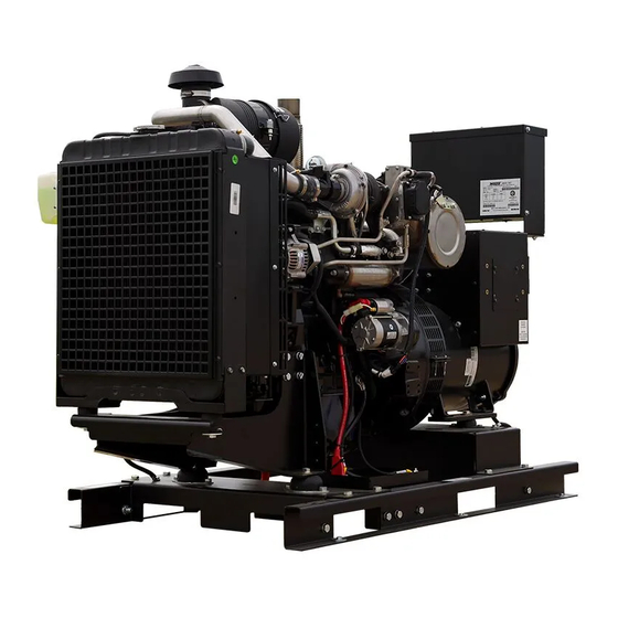
DE39Y4-XX/4
GENERATOR
INSTALLATION AND
OPERATORS MANUAL
COPY YOUR MODEL AND SERIAL NUMBER HERE
No other WINCO generator has the same serial number as
yours.
If you should ever need to contact us concerning this unit, it
will help us to respond to your needs faster.
MODEL _____________________________________________
16200-056
SERIAL NUMBER _____________________________________
PURCHASE DATE ____________________________________
DEALER NAME ______________________________________
DEALER PHONE # ___________________________________
www.wincogen.com
Advertisement
Table of Contents

Related Manuals for Winco DE39Y4 /4 Series


Summary of Contents for Winco DE39Y4 /4 Series
- Page 1 INSTALLATION AND OPERATORS MANUAL COPY YOUR MODEL AND SERIAL NUMBER HERE No other WINCO generator has the same serial number as yours. If you should ever need to contact us concerning this unit, it will help us to respond to your needs faster.
-
Page 2: Table Of Contents
TABLE OF CONTENTS SAVE THESE INSTRUCTIONS TROUBLE SHOOTING TABLES SAFETY INFORMATION WIRING SIZE TABLE SAFETY DEFINITIONS MANUAL START WIRING DIAGRAM SPECIFICATIONS DSE7310 WIRING DIAGRAM DE39Y4 GENERATOR CONNECTIONS INTRODUCTION LIMITED WARRANTY TESTING POLICY Rated output of generator is based on engineering tests of typical units, and is subject to, and limited by, the temperature, altitude, fuel, and other conditions specified by the manufacturer of applicable engines. -
Page 3: Using This Manual
Should you experience a problem please follow the “Troubleshooting Tables” near the end of this manual. The warranty listed in the manual describes what you can expect from WINCO should you need service assistance in the future. OPM-181/A... -
Page 4: Safety Information
SAFETY INFORMATION IMPORTANT SAFETY INSTRUCTIONS This engine generator set has been designed and DANGER: FIRE HAZARD manufactured to allow safe, reliable performance. Poor Gasoline and other fuels present a hazard of possible maintenance, improper or careless use can result in explosion and/or fire. -
Page 5: Specifications
SPECIFICATIONS DE39Y4 STANDBY PRIME VOLTS WATTS AMPS WATTS AMPS 120/240 1-PH 36,000 36.0 32,400 32.4 120/208 3-PH 39,000 48.75 35,100 43.88 120/240 3-PH 39,000 48.75 35,100 43.88 277/480 3-PH 39,000 48.75 35,100 43.88 346/600 3-PH 39,000 48.75 35,100 43.88 GENERATOR RESISTANCE (all value at 22°C) Model Stamford S1L2-R1... -
Page 6: Introduction
Go to the WINCO website for a list of engine dealers temperature, altitude, fuel, and other conditions specified (wincogen.com) or contact the WINCO Service Department. -
Page 7: Preparing The Unit
This must be completed and NOT PLACE FUEL IN THE TANK PRIOR TO LIFTING. returned to WINCO Inc. within 180 days of the factory invoice date. If this form is not returned, the Warranty may be voided. -
Page 8: Installation
When installing, ensure that the radiator is at least 0.75” from a solid surface such as a wall or duct. The radiator The WINCO installation manual OPM-112 contains is mounted on rubber vibration isolators that allow it to additional information on indoor installations and move. -
Page 9: Exhaust Installation
EXHAUST INSTALLATION INSTALLING THE FUEL LINE WARNING: PERSONAL INJURY Engine-generator sets are properly adjusted before they leave the factory. Connecting a fuel supply with adequate Improper exhaust installation will allow dangerous gases supply volume is critical to reliable operation. Diesel units to seep into enclosed spaces causing a hazard to your with optional base mounted fuel tanks are pre-plumbed to health and/or death. -
Page 10: Customer Connections
The following table gives you the recommended circuit WARNING: EQUIPMENT DAMAGE breaker size specifications. See actual breaker for wire When installing a three phase 240 Volt system, be sure capabilities and torque specifications and restrictions. you know which lead is high voltage ‘wild’ leg (208 Volt to Watts Voltage Phase... -
Page 11: Grounding
All communication and DC wiring should be run in separate conduit from AC wiring. To install the wires, reference Your WINCO generator ships with a bonded neutral. the following picture. Use a small flat head screwdriver to When mounted to a vehicle to safely distribute power it is push the release spring inside the square hole (A). -
Page 12: Serial Communication
RS485. The ports are wired onto the back of the DSE7310. In order to finalize communication the program will need to be adjusted using the free DSE configuration software to enable the commutation. Contact Winco service for a list of register values. OPM-181/A... -
Page 13: Installing The Battery
INSTALLING THE BATTERY CAUTION WARNING In the following battery installation procedure, check to be The electrolyte is diluted sulfuric acid that is harmful to the sure the engine control is in the “stop” position. This should skin and eyes. It is electrically conductive and corrosive. be your last step before initial start-up. -
Page 14: Block Heater
This charger is mounted under the customer connection on the control side of the generator. The charger will need to be plugged to a customer’s power source, using a customer supplied heavy duty, UL approved extension cord. The receptacle is to be powered by a GFCI circuit and installed in accordance to the US National Electric Code. -
Page 15: Starting Procedure
We have partnered with a national lubrication oil PRE-START CHECK LIST manufacturer to give you access to Winco private branded premium oil available at comparable prices to conventional There is a Pre-Start & Warranty Form that must be filled out oils. -
Page 16: Manual Start Panel
MANUAL START PANEL Low fuel lamp will be steady when fuel level has reached 20% or less. It will flash when the fuel level is 5% or less. (Standard) The engine will shut down if the fuel level is at 5% or less. This generator comes standard with a manual start control In the event that the upper left and upper right icons are panel. -
Page 17: Dse7310 Mkii
DSE7310 MKII WARNINGS Warnings are non-critical alarm conditions. They do not (Optional) affect the operation of the generator system, they serve to draw the operator’s attention to an undesirable CAUTION condition. Warning alarms are self-resetting when the If the DSE7310 is being replaced with a manual start panel, fault condition is removed. -
Page 18: Control Power
With the engine running smoothly check the no load voltage and frequency on the digital display. The voltage should match the nameplate and a frequency of 59.5 to 60.5 hertz (Hz). If you have the proper voltage at the generator the next step is to check the voltage at the generator terminals in the Automatic Transfer Switch. -
Page 19: Operating Conditions
OPERATING CONDITIONS NORMAL OPERATION This generator set is designed to be operated under load and the accumulation of operating hours without load can cause unburned fuel from the combustion chamber to build up in the exhaust system. This is called wet stacking and can result in fouled injectors and carbon buildup in the exhaust pipes, turbo and exhaust valves. -
Page 20: Maintenance
Only change oil when the engine is not running and is at a low temperature in order to avoid the risk of burns. WINCO has plumbed an oil drain valve to the outside of the unit. Attach a customer supplied 5/8” hose to conveniently run the oil to a drip pan or suitable container for catching the oil. -
Page 21: Draining Water Separator
DRAINING WATER SEPARATOR CLEANING RADIATOR DANGER The surfaces of the radiator come into contact with the outside air and can be subject to deposits and impurities. Diesel fuel is flammable and explosive under certain Clean in accordance with the engine operator’s manual conditions. -
Page 22: Maintenance Schedule
MAINTENANCE SCHEDULE Daily Check and refill engine coolant Check indicators Check lubricating oil level Check and refill fuel tank levels Visual check Every 50 Hours Check and adjust cooling fan V-belt (first time) Check battery Drain water separator Every 250 Hours Check and clean radiator fins Check and adjust cooling fan V-belt (2nd and after) Clean or replace air cleaner element... -
Page 23: Save These Instructions 3 Trouble Shooting Tables
TROUBLE SHOOTING TABLES Problem Possible Causes Unit will not crank when Digital genset not in AUTO power fails Transfer control switch not in AUTOMATIC position Incorrect wiring between ATS and genset Defective control relay in ATS Fuse(s) blown in the DSE 7310 Defective DSE 7310 Loose or dirty battery terminals Defective starter... -
Page 24: Wiring Size Table
WIRING SIZE TABLE The table below is based on Table 310.16 in the National Electric Code 2020 edition. Allowable ampacitier of insulated conductrs rated 0 through 2000V, 75°C through 90°C. Not more than three current-carrying conductors in Raceway, Cable, or Earth (direct buried). Adjust for 40°C (104°F) ambient temperature. - Page 25 MANUAL START PANEL WIRING DIAGRAM OPM-181/A...
- Page 26 DSE7310 WIRING DIAGRAM OPM-181/A...
-
Page 27: Generator Connections
GENERATOR CONNECTIONS THREE PHASE AC WIRE HIGH AND LOW WYE OPM-181/A... -
Page 28: Three Phase Ac Wiring- Delta
SINGLE PHASE 311 WINDING THREE PHASE AC WIRING- DELTA OPM-181/A... -
Page 29: Limited Warranty
Air cooled units purchased for stock have 1 year to be sold. The warranty to the original retail customer commences on the date of sale of the product to them. All liquid cooled units have 180 days from the Winco invoice to submit a start up date. If no startup form is submitted, then warranty period starts on the Winco invoice date unit was sold. -
Page 30: What Is Not Covered By Warranty
Note 2: 3rd Year warranty coverage is parts only/no labor. Note 3: Round trip mileage is limited to 200 miles per trip and a total of 2 trips per repair unless authorized in writing by the WINCO Service Dept. - Page 31 THIS PAGE LEFT INTENTIONALLY BLANK OPM-181/A...
- Page 32 225 S. CORDOVA AVE • LE CENTER, MN 56057 Sales: 507-357-6821• sales@wincogen.com Service: 507-357-6831 • service@wincogen.com www.wincogen.com OPM-181/A...
Need help?
Do you have a question about the DE39Y4 /4 Series and is the answer not in the manual?
Questions and answers