Table of Contents
Advertisement
Quick Links
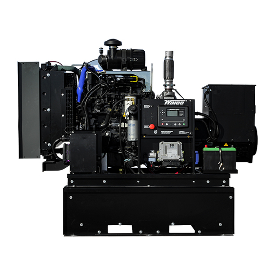
DE50F4
GENERATOR
INSTALLATION AND
OPERATORS MANUAL
COPY YOUR MODEL AND SERIAL NUMBER HERE
No other WINCO generator has the same serial number as yours.
If you should ever need to contact us on this unit, it will help us to
respond to your needs faster.
MODEL __________________________________________________
SERIAL NUMBER _________________________________________
PURCHASE DATE _________________________________________
DEALER NAME ___________________________________________
DEALER PHONE # ________________________________________
www.wincogen.com
Advertisement
Table of Contents

Related Manuals for Winco DE50F4


Summary of Contents for Winco DE50F4
- Page 1 OPERATORS MANUAL COPY YOUR MODEL AND SERIAL NUMBER HERE No other WINCO generator has the same serial number as yours. If you should ever need to contact us on this unit, it will help us to respond to your needs faster.
-
Page 2: Table Of Contents
Should you experience a problem please follow the “Troubleshooting Tables” near the end of this manual. The warranty listed in the manual describes what you can expect from WINCO should you need service assistance in the future. OPM-143/E... -
Page 3: Safety Information
SAFETY INFORMATION F. Follow local codes for closeness to combustible material. SAVE THESE INSTRUCTIONS 3. DEADLY EXHAUST GAS - This engine generator set has been designed and Exhaust fumes from any gasoline engine contain carbon manufactured to allow safe, reliable performance. Poor monoxide, an invisible, odorless and deadly gas that must maintenance, improper or careless use can result in be mixed with fresh air. -
Page 4: Specifications
SPECIFICATIONS DE50F4 STANDBY PRIME VOLTS WATTS AMPS WATTS AMPS 120/240 1-PH 45,000 40,500 40.5 120/208 3-PH 47,000 43,200 120/240 3-PH 47,000 43,200 277/480 3-PH 47,000 43,200 346/600 3-PH 47,000 43,200 GENERATOR RESISTANCE (all value at 22°C) Model Stamford UCI224E Winding Group Rotor 0.69 Ω... -
Page 5: Testing Policy
Before any generator is shipped from the factory, it is fully Go to the WINCO website for a list of engine dealers checked for performance. The generator is loaded to its (wincogen.com) or contact the WINCO Service Department. -
Page 6: Preparing The Unit
This must be completed and set into place. DO NOT PLACE FUEL IN THE TANK PRIOR returned to WINCO Inc. within 180 days of the factory TO LIFTING. invoice date. If this form is not returned, the Warranty may be voided. -
Page 7: Installation
0.75 in. to the edge of the structure or other solid surfaces. The radiator is mounted on rubber vibration The WINCO installation manual OPM-112 contains isolators that allow it to move. Placing the duct flange too additional information on indoor installations and... -
Page 8: Exhaust Installation
EXHAUST INSTALLATION INSTALLING THE FUEL LINE WARNING: PERSONAL INJURY Engine-generator sets are properly adjusted before they Improper exhaust installation will allow dangerous gases to leave the factory. Connecting a fuel supply with adequate seep into enclosed spaces causing a hazard to your health supply volume is critical to reliable operation. -
Page 9: Grounding
VEHICLE-MOUNTED GENERATOR exceed the amperage rating of the circuit breaker installed. Your WINCO generator ships with a bonded neutral. When mounted to a vehicle to safely distribute power it is necessary that the generator frame is bonded to the vehicle frame. -
Page 10: Dc Wiring
RS485. The ports are wired onto the back of the DSE7310. In order to finalize communication the program will need to be adjusted using the free DSE configuration software to enable the commutation. Contact Winco service for a list of REMOTE START register values. -
Page 11: Servicing Batteries
DO NOT open or mutilate the battery. Released electrolyte NOTE: Always make sure that a new battery is fully charged is known to be harmful to the skin and eyes and to be very before installing it on a generator set. Failure to do so toxic. -
Page 12: Starting Procedure
We have partnered with a national lubrication oil dipstick (1) using a clean cloth and then put it back into manufacturer to give you access to Winco private branded its seat (2). Remove the dipstick (1) again and check the premium oil available at comparable prices to conventional level. -
Page 13: Control Layout
CONTROL LAYOUT MANUAL MODE 1. Press and release the MANUAL MODE button. The small LED light next to it should come on. Note: There is no start delay in this mode of operation. 2. Press and release the green START ENGINE button. The DSE 7310 will send two signals to the engine. -
Page 14: Operating Conditions
button will stop the unit but only after the cool down To avoid wet stacking the operating temperatures must be timers have timed out and there is no remote start signal kept high enough. The best way to do this is to ensure that being sent to the unit. -
Page 15: Maintenance
We have partnered with a national lubrication oil 2. Replace the oil filter (1) and gasket (2). manufacturer to give you access to Winco private branded premium oil available at comparable prices to conventional 3. Carefully clean the surfaces of the support that are in oils. -
Page 16: Changing Air Filter
CHANGING AIR FILTER CLEANING RADIATOR The surfaces of the radiator come into contact with the outside air and can be subject to deposits and impurities. Clean in accordance to the maintenance schedule with compressed air or steam. Do NOT remove filter while engine is running. 1. -
Page 17: Storage
STORAGE Using Illustration 2: 1. Loosen the nut (2) PREPARING THE ENGINE FOR A LONG PERIOD OF INACTIVITY 2. Disconnect the fittings (1)(4). In the case of a planned period of inactivity that lasts longer 3. Remove the vapor recirculation pipe (3). than two months, to prevent the interior parts of the engine and some components of the injection system from oxidizing, prepare the engine as follows:... -
Page 18: Trouble Shooting Tables
TROUBLE SHOOTING TABLES MAINTENANCE SCHEDULE Problem Possible Causes Checks In Period of Use Frequency Unit will not crank when Digital genset not in AUTO Check for water in the fuel Pre-Filter Daily power fails Transfer control switch not in AUTOMATIC position Check Air-Restriction Indicator on Filter Daily Incorrect wiring between ATS and genset Engine Oil Level... -
Page 19: Engine Codes
ENGINE CODES FMI Test Translation The electrical Signal of the EGR Valve position sensor is monitored. In case of defect recognition a replacement value is 1B-3 taken. The electrical Signal of the EGR Valve position sensor is monitored. In case of defect recognition a replacement value is 1B-4 taken. - Page 20 FMI Test Translation The Fuel Rail pressure control is executed with a device: Metering Unit (MeUn) as feeding quantity control and an 9D-12 overpressure valve allocate in the rail (PRV). Dataset Interlock Feature is used to prevent the flashing of unintended datasets on to the ECU during any SW upgrades A6-2 in field.
- Page 21 FMI Test Translation Hardware errors in the injectors and respective ECM power stages are investigated. Diagnostic procedure uses pattern detection to identify specific errors and trigger appropriate substitute reaction. The behavior pattern describes in a 28C-5 bit mask different detected problem (overcurrent, command collision, RAM error,short circuit,..) when the expected combination of errors is detected (measured and reference pattern are matching) a failure is detected.
- Page 22 FMI Test Translation Engine Starter is controlled by two relays actuators one for Low Side and one for High Side. Both power stages are 2A4-6 monitored by Hardware for electric failures. The Engine Position Management module is responsible for signals from camshaft and crankshaft sensor evaluation: angle and speed determination, signal plausibility and quality are monitored by this module.
- Page 23 FMI Test Translation The Power stage of EGR Valve actuator is monitored by Hardware for electric failures. The Power stage of electric EGR Valve actuator (H-Bridge) is monitored by Hardware for electric failures. The H-Bridge has 2 switches (High side and Low side). Each circuit is monitored separately. The Power stage of electric EGR Valve actuator (H-Bridge) is monitored by Hardware for electric failures.
- Page 24 FMI Test Translation 4009 The Power stage of Fuel Filter heater is monitored by Hardware for electric failures. FA9-5 4009 The Power stage of Fuel Filter heater is monitored by Hardware for electric failures. FA9-6 The electrical Signal of the Oxi Cat temperature upstream sensor is monitored. In case of defect recognition a substitute 4765 129D-3 value is taken.
-
Page 25: Wiring Size Table
WIRING SIZE TABLE The table below is based on Table 310.15 (B) (16) in the National Electric Code 2014 edition. Allowable ampacitier of insulated conductors rated 0 through 2000V, 75°C through 90°C. Not more than three current-carrying conductors in Raceway, Cable, or Earth (direct buried). Adjust for 40°C (104°F) ambient temperature. -
Page 26: Engine Harness
ENGINE HARNESS OPM-143/E... -
Page 27: Dse7310 Wiring Diagram
DSE7310 WIRING DIAGRAM OPM-143/E... -
Page 28: Wiring Diagrams
WIRING DIAGRAMS THREE PHASE AC WIRE HIGH AND LOW WYE THREE PHASE AC WIRING- DELTA SINGLE PHASE 311 WINDING OPM-143/E... -
Page 29: Ca Emission Control Warranty
CALIFORNIA EMISSION CONTROL WARRANTY STATEMENT YOUR WARRANTY RIGHTS AND OBLIGATIONS California Air Recourses Board and FPT Industrial S.p.A. are pleased to explain the emission control system warranty on 2018 to 2020 off-road engines. In California, new heavy-duty off-road engines must be designed, built, and equipped to meet the state’s stringent anti-smog standards. -
Page 30: Environmental Warranty
US ENVIRONMENTAL WARRANTY STATEMENT FPT Industrial S.p.A. warrants to the ultimate purchaser and each subsequent purchaser that the engine is designed, built, and equipped so as to conform with US Environmental Protection Agency (EPA) regulations applicable at the time of manufacture and that it is free from defects in workmanship or material which would cause it not to meet these regulations for a period of time: 2 years or 1,500 hours of operation, whichever occurs first, for engines less than 19kW (25HP) 5 Years or 3,000 hours of operation, whichever occurs first, for engines greater than or equal to 19kW (25 HP) -
Page 31: Revalidation Of Warranty
(12) months afterwards for a maximum of twenty-four (24) months for warranty coverage to be available, and provide written confirmation to WINCO inc that the engine was revalidated. -
Page 32: Limited Warranty
Warranty service may be performed by an authorized WINCO Inc. service center only. Service work performed by unauthorized persons will void all warranties. WINCO Inc. shall not be liable for any claim in an amount greater than the purchase price of the product. In no event shall WINCO Inc. be held liable for any special, indirect, consequential or liquidated damages.
Need help?
Do you have a question about the DE50F4 and is the answer not in the manual?
Questions and answers