Advertisement
Quick Links
Instruction Manual
Website:
www.perlesmith.com
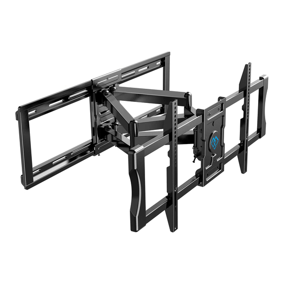
TV Wall Mount
Model:PSLF6
Thank you for choosing this Perlesmith product! At Perlesmith
we strive to provide you with the best quality products and
services in the industry. Please share your experience of our
product with others at www.perlesmith.com/pages/reviews if
you are satisfied. Should you have any issues, please don't
hesitate to contact us.
Technical Support:
1-800-556-6806 Mon-Fri 10am - 5pm (PST) (USA) (CAN)
Other Info:
supportus@perlesmith.com (US)
supportca@perlesmith.com (CA)
V2.0
Advertisement

Related Manuals for Perlesmith PSLF6


Summary of Contents for Perlesmith PSLF6
- Page 1 Instruction Manual V2.0 Model:PSLF6 Thank you for choosing this Perlesmith product! At Perlesmith we strive to provide you with the best quality products and services in the industry. Please share your experience of our product with others at www.perlesmith.com/pages/reviews if you are satisfied.
-
Page 2: Weight Restrictions
Minimum VESA pattern: 200mm/8 in.(W)x100mm/4 in.(H) If your TV VESA is greater than 600x400 mm/24x16 in. or less than VESA 200x100mm/8x4in., this mount is NOT compatible. If this mount is NOT compatible, please contact customer service at supportus@perlesmith.com (US)/supportca@perlesmith.com (CA) to find a compatible mount. -
Page 3: Supplied Parts And Hardware
Product Support line at 1-800-556-6806 or customer service at supportus@perlesmith.com (US)/supportca@perlesmith.com (CA) • Please note: Not all hardware included in this package will be used. Supplied Parts and Hardware for Step 1... - Page 4 Bolts [Only one bolt size fits your TV] Note: The bolts are shown in accordance with the actual size M6 x 15mm M6 x 35mm [D1] [D2] M8 x 15mm M8 x 25mm [E1] [E2] M8 x 35mm M8 x 50mm [E3] [E4] Supplied Parts and Hardware for Step 2...
- Page 5 Washer CAUTION! These anchors are for Wall concrete or brick walls Anchor ONLY. DO NOT use them in drywall or wood studs. Supplied Parts and Hardware for Step 3 to Step 6 Front Support Arm Assembly Bolt Bolt Allen Key [F1] [F2] Step 1 Secure the TV Brackets to TV...
- Page 6 Note: If necessary, the spacers can be used in multi-layer. If the installation fails after trying various methods, please contact customer service at supportus@perlesmith.com (US)/supportca@perlesmith.com (CA) CAUTION: Ensure the TV brackets [03] are EQUALLY CENTERED on your TV AND securely fastened in place.
- Page 7 Option C (For TV with A “Bump”) Spacers may be necessary for 2 holes ONLY. D1/E1 D2/E2/E3/E4 C1/C2/C3 Alternate Spacer Setups Option D For cable interference or inset holes, use spacers [06] to create extra space between the TV and TV brackets C1/C2/C3 D2/E2/E3/E4 Alternate Spacer Setups...
- Page 8 Step 2 Attach the Wall Plate [01] to Wall For wood stud installation, follow STEP 2A For concrete installation, follow STEP 2B Step 2A Wood Stud Option WARNING: ●Avoid potential personal injury or property damage! DO NOT over-tighten the lag screws [A1]. Tighten the lag screws [A1] only until the washers [A2] are pulled firmly against the wall plate.
- Page 9 2A-3 Drill 4 pilot holes using a 7/32 in.(5.5 mm) diameter drill bit. Make sure the depth is not less than 2 9/16 in.(65mm). 2 9/16 in.(65mm) ø7/32 in.(5.5 mm) 2A-4 Install the wall plate using lag screws [A1] and washer [A2]. Tighten the lag screws [A1] only until the washers [A2] are pulled firmly against the wall plate.
- Page 10 2B-1 Position the wall plate template [04] at your desired height, level the wall plate template and mark the pilot hole locations. 2B-2 Drill 6 pilot holes using a 3/8 in.(10mm)diameter drill bit. Make sure the depth is not less than 2 3/4 in.(70mm).
- Page 11 Step 3 Secure the Arm Assembly [02] to Wall Plate [01] 1. Hang the arm assembly [02] to wall plate [01]. 2. Shift the arm assembly [02] along the wall plate [01] to your desired position. 3. Secure the arm assembly [02] to wall plate [01] using bolts [F1]. Note: The bolts [F1] need to be tightened hard.
- Page 12 Step 5 Hang the TV onto the Front Support Remove the preassembled bolt [S] and save to use in 5-2 Phillips Screwdriver (Not lncluded) Hang the TV with brackets [03] onto the front support [08] Screwdriver (Not lncluded) Press the safety locks down, then fasten the HEAVY! You may need removed bolts [S] assistance with this step.
- Page 13 CAUTION! DO NOT over-loosen these four nuts when Level adjusting the level angle to prevent the TV Allen Key from falling off. 1.Loosen the bolt [F2] . 2.Level your TV. 3.Tighten the bolt [F2] to secure the TV in place.
- Page 14 Note: Please take off the TV before shifting Horizontal the arm assmebly along the wall plate Shift Take off TV Loosen bolts [S] To better position your mount and TV on your wall, the mount can be horizontal shifted left to right by following these steps. 1.
- Page 15 Thank you again choosing this Perlesmith product! All of us at Perlesmith do appreciate your product purchase. We hope that you are as happy with your product as we designing and manufacturing it for you. We strive to provide you with the best quality products and services in the industry.
- Page 16 Perlesmith offers products in these categories AV Shelves Anti-tip Straps TV Stands Speaker Stands TV Carts Full Motion Mounts Tilt Mounts Corner Mounts Please remember us when you need one.
Need help?
Do you have a question about the PSLF6 and is the answer not in the manual?
Questions and answers