Table of Contents
Advertisement
Quick Links
This document is the EVM user guide for the TS3A227E-EVM which provides an easy evaluation of TI's
autonomous audio jack switch with integrated key-press detection and power off noise removal.
spacer
1
2
...................................................................................................................
3
3.1
4
4.1
4.2
4.3
4.4
4.5
4.6
4.7
5
6
7
7.1
7.2
7.3
7.4
7.5
7.6
8
8.1
8.2
8.3
9
1
2
3
4
.....................................................................................................................
5
Translator
6
On-Board MICBIAS Output
7
8
External CODEC Interface
9
10
11
LaunchPad, Code Composer Studio are trademarks of Texas Instruments.
Submit Documentation Feedback
............................................................................................................
.....................................................................................
.................................................................................
.................................................................................................................
...........................................................................................................
............................................................................................................
........................................................................................
....................................................................................................
.........................................................................................
...........................................................................................................
...........................................................................................................
...............................................................................................................
.................................................................................
.....................................................................................................
................................................................................................
......................................................................................................
..........................................................................................................
....................................................................................................
........................................................................................................
....................................................................................................
...........................................................................................
....................................................................................................
.........................................................................................................
..............................................................................................
.................................................................................................
........................................................................................................
..................................................................................................
..........................................................................................
......................................................................................
................................................................................................
Copyright © 2014, Texas Instruments Incorporated
TS3A227E EVM User's Guide
Contents
...............................................................................
............................................................................
..............................................................
...................................................................
..........................................................................
List of Figures
User's Guide
SLVUAD9 - December 2014
2
2
3
3
4
4
5
6
6
7
7
8
9
11
12
12
14
16
17
18
18
19
19
20
22
25
3
4
5
6
6
7
7
8
9
9
10
1
Advertisement
Table of Contents

Related Manuals for Texas Instruments TS3A227E


Summary of Contents for Texas Instruments TS3A227E
-
Page 1: Table Of Contents
User's Guide SLVUAD9 – December 2014 TS3A227E EVM User's Guide This document is the EVM user guide for the TS3A227E-EVM which provides an easy evaluation of TI's autonomous audio jack switch with integrated key-press detection and power off noise removal. spacer Contents ...................... -
Page 2: About This Manual
..................TS3A227E-EVM Bill of Materials About this Manual This user’s guide describes the TS3A227E evaluation module (EVM) and its intended use. This guide contains the EVM schematics, bill of materials, and board layer information. Information About Cautions and Warnings The information in a caution or a warning is provided for personal protection. Read each caution and warning carefully. -
Page 3: Introduction
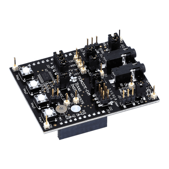
Introduction The TS3A227E-EVM is an evaluation module for TI's autonomous audio jack switch with integrated key- press detection and power off noise removal. Designed to interact with the audio jack, the device automatically detects the presence of 3- or 4-pole audio accessories and also features an integrated switch matrix for automatic routing of the MICBIAS, codec ground sense, and ground connections. -
Page 4: Ts3A227E-Evm Connections Overview
TS3A227E Design Under Test (DUT) The TS3A227E audio lines are connected to audio jack J4. Plug a headset into audio jack J4 for testing. The audio jack used on the EVM is normally a closed jack that has the wrong transition polarity for an insertion event (low to high). -
Page 5: Power
TS3A227E-EVM Connections Overview www.ti.com Power The TS3A227E-EVM derives its power from the LaunchPad. The EVM board power is labeled VCC in the schematic and the power supplied to the TS3A227E is labeled VDD. Header connection explanations follow: • Header J1 provides a point to check VCC or to provide the board power if the LaunchPad is not being used. -
Page 6: Test Points
Figure 4. Breakout Test Point Headers Translator Because the TS3A227E VDDIO supply can vary from 1.8 V to 4.5 V, a translator is needed to translate the VDDIO voltage domain to the LaunchPad 3.6-V domain. U3 provides this functionality. If the LaunchPad is not used, remove the jumpers on J27. -
Page 7: On-Board Micbias Output
7.3.1. By placing a jumper on both headers J15 and J20, the matrix is attached to the TS3A227E SLEEVE and RING2 pins allowing the keys to be used. The on-board microphone is used to simulate a headset microphone in parallel with the keys and can be disconnected by removing the jumper on J16. -
Page 8: External Codec Interface
External CODEC Interface J10 provides a means to connect an external codec to the TS3A227E-EVM through a 3.5-mm jack. J12 is provided to switch the microphone and ground of the EVM between the SLEEVE and RING2 pins. Shorting pins 1-2 and pins 3-4 connects MICP to RING2 and SLEEVE to ground. Shorting pins 2–4 and 1–3 connects MICP to SLEEVE and RING2 to ground. -
Page 9: Launchpad Setup
3. Connect the LaunchPad to a computer with a USB-to-mini cable. A green LED and a red LED now turn on as shown in Figure SLVUAD9 – December 2014 TS3A227E EVM User's Guide Submit Documentation Feedback Copyright © 2014, Texas Instruments Incorporated... -
Page 10: Launchpad Led Indicators
7. CCS can also be used as a firmware development/experimentation platform and the EVM/GUI will work while using the debugging functionality of Code Composer Studio. 8. If the LaunchPad is running and the TS3A227E-EVM daughter board is disconnected, the I communication fails. Pause the debugger, reset the MSP430, and then rerun the code. -
Page 11: Installing The Gui
Figure 12. Application Install - Security Warning Window 4. After the installation finishes, the GUI opens. The GUI is illustrated in Figure Figure 13. TS3A227E-EVM GUI Window If the window shown in Figure 14 appears, verify that the EVM is plugged into the PC. -
Page 12: Using The Gui
Figure 14. COM PORT Detection Error Window 5. When launching the GUI in the future, open it by double clicking the TS3A227E.application file. Using the GUI This section includes instructions for connecting the LaunchPad to the EVM and PC, GUI window descriptions, GUI operation, headset development, power off noise removal evaluation, and slow plug-in issues. - Page 13 3. Connect the LaunchPad to the PC. A blue LED now lights up along with the red and green LEDs on the LaunchPad. Figure 16. LaunchPad LED Indicators SLVUAD9 – December 2014 TS3A227E EVM User's Guide Submit Documentation Feedback Copyright © 2014, Texas Instruments Incorporated...
-
Page 14: Gui Area Descriptions And Use
Reserved toggles that bit. If Auto Write on Click is checked, clicking on a bit also sends a command to the MSP430 to write the value entered to the TS3A227E. – For example, if register 0x03 currently has the value 0x01 and bit 1 of that register is clicked, bit 1 toggles from a value of ‘0’... - Page 15 • The orange section runs algorithms to determine the real-world values corresponding to the output of the TS3A227E, that is, the Accessory Detection box in the top left monitors the Accessory Type register (0x08) to determine what is attached. •...
-
Page 16: Gui Operation
‘1’ in the register map. The GUI still writes the existing value to the register. If Auto Write on Click is disabled, nothing happens. 7.3.1 Using the TS3A227E-EVM On-Board Keys Make sure nothing is inserted into the EVM jack. 1. Setup the jumpers on the EVM to the positions listed in Table Table 2. -
Page 17: Using The Ts3A227E To Develop A Headset
Once setup, attach the parallel or resistor between the SLEEVE and RING2 pins, not between one of the SLEEVE/RING2 pins and ground. The TS3A227E sees this drop in voltage on the MIC line and detects the parallel resistance combination. -
Page 18: Power Off Noise Removal Evaluation
TI recommends developers that use the TS3A227E utilize the EVM test points for the audio jack pins and connect the EVM to the audio jack that is planned for implementation. This allows the system designer to test how the TS3A227E and the audio jack perform together and makes changes as necessary. -
Page 19: Board Documentation
/MIC_PRESENT /INT RING1 MICP RING2 Key 1-4 resistance are calculated so that when in parallel with a 2.2 kohm mic the equivalent resistance seen by the TS3A227E is within the bins shown above MSP430 LaunchPad Jumper connectors RING2 Key1 Key2... -
Page 20: Bill Of Materials
Board Documentation www.ti.com Bill of Materials Table 3 lists the TS3A227E-EVM BOM. Table 3. TS3A227E-EVM Bill of Materials Designator Quantity Value Description Package Reference Part Number Manufacturer !PCB1 Printed Circuit Board HVL094 C1, C3, C5, C7 CAP, CERM, 1uF, 6.3V, +/-10%, X7R, 0603... -
Page 21: Slvuad9 - December 2014
Board Documentation www.ti.com Table 3. TS3A227E-EVM Bill of Materials (continued) Designator Quantity Value Description Package Reference Part Number Manufacturer Autonomous Audio Accessory Detection and Configuration Switch, RVA0016A TS3A227ERVA Texas Instruments RVA0016A Single Output LDO, 80 mA, Adjustable 1.2 to 8.8 V Output, 2.5 to 10... -
Page 22: Pcb Layout
Board Documentation www.ti.com PCB Layout Figure 23 through Figure 25 illustrate the TS3A227E-EVM PCB layouts. Figure 22. Top Copper TS3A227E EVM User's Guide SLVUAD9 – December 2014 Submit Documentation Feedback Copyright © 2014, Texas Instruments Incorporated... - Page 23 Board Documentation www.ti.com Figure 23. Ground Plane (Negative Image) SLVUAD9 – December 2014 TS3A227E EVM User's Guide Submit Documentation Feedback Copyright © 2014, Texas Instruments Incorporated...
- Page 24 Board Documentation www.ti.com Figure 24. Power Plane (Negative Image) TS3A227E EVM User's Guide SLVUAD9 – December 2014 Submit Documentation Feedback Copyright © 2014, Texas Instruments Incorporated...
-
Page 25: Related Documentation
• Datasheet link: http://www.ti.com/lit/ds/symlink/ts3a227e.pdf • Link to software: TBD • Link to Code Composer Studio Wiki: http://www.ti.com/tool/CCSTUDIO • Link to MSP430 LaunchPad: http://www.ti.com/tool/msp-exp430g2 SLVUAD9 – December 2014 TS3A227E EVM User's Guide Submit Documentation Feedback Copyright © 2014, Texas Instruments Incorporated... - Page 26 STANDARD TERMS AND CONDITIONS FOR EVALUATION MODULES Delivery: TI delivers TI evaluation boards, kits, or modules, including any accompanying demonstration software, components, or documentation (collectively, an “EVM” or “EVMs”) to the User (“User”) in accordance with the terms and conditions set forth herein. Acceptance of the EVM is expressly subject to the following terms and conditions.
- Page 27 FCC Interference Statement for Class B EVM devices NOTE: This equipment has been tested and found to comply with the limits for a Class B digital device, pursuant to part 15 of the FCC Rules. These limits are designed to provide reasonable protection against harmful interference in a residential installation.
- Page 28 【無線電波を送信する製品の開発キットをお使いになる際の注意事項】 本開発キットは技術基準適合証明を受けておりません。 本製品のご使用に際しては、電波法遵守のため、以下のいずれかの措置を取っていただく必要がありますのでご注意ください。 1. 電波法施行規則第6条第1項第1号に基づく平成18年3月28日総務省告示第173号で定められた電波暗室等の試験設備でご使用 いただく。 2. 実験局の免許を取得後ご使用いただく。 3. 技術基準適合証明を取得後ご使用いただく。 なお、本製品は、上記の「ご使用にあたっての注意」を譲渡先、移転先に通知しない限り、譲渡、移転できないものとします。 上記を遵守頂けない場合は、電波法の罰則が適用される可能性があることをご留意ください。 日本テキサス・インスツルメンツ株式会社 東京都新宿区西新宿6丁目24番1号 西新宿三井ビル 3.3.3 Notice for EVMs for Power Line Communication: Please see http://www.tij.co.jp/lsds/ti_ja/general/eStore/notice_02.page 電力線搬送波通信についての開発キットをお使いになる際の注意事項については、次のところをご覧くださ い。http://www.tij.co.jp/lsds/ti_ja/general/eStore/notice_02.page SPACER EVM Use Restrictions and Warnings: 4.1 EVMS ARE NOT FOR USE IN FUNCTIONAL SAFETY AND/OR SAFETY CRITICAL EVALUATIONS, INCLUDING BUT NOT LIMITED TO EVALUATIONS OF LIFE SUPPORT APPLICATIONS.
- Page 29 Notwithstanding the foregoing, any judgment may be enforced in any United States or foreign court, and TI may seek injunctive relief in any United States or foreign court. Mailing Address: Texas Instruments, Post Office Box 655303, Dallas, Texas 75265 Copyright © 2014, Texas Instruments Incorporated...
- Page 30 IMPORTANT NOTICE Texas Instruments Incorporated and its subsidiaries (TI) reserve the right to make corrections, enhancements, improvements and other changes to its semiconductor products and services per JESD46, latest issue, and to discontinue any product or service per JESD48, latest issue.
Need help?
Do you have a question about the TS3A227E and is the answer not in the manual?
Questions and answers