Table of Contents
Advertisement
Quick Links
This document outlines the basic steps and functions that are required for the proper operation of the
TSW6011 evaluation module (EVM) system. The
used to demonstrate a
octal analog-to-digital converter (ADC). This guide helps the user to evaluate the performance of various
modes of operation of the TSW6011EVM. Throughout this document, the term evaluation module and the
abbreviation EVM are synonymous with the TSW6011EVM.
.....................................................................................................................
1
1.1
1.2
1.3
2
2.1
3
3.1
3.2
4
4.1
4.2
4.3
4.4
4.5
5
5.1
5.2
5.3
Register 3
5.4
.......................................................................................................................
1
2
3
4
5
6
7
8
9
10
MATLAB is a registered trademark of The MathWorks.
All other trademarks are the property of their respective owners.
SLWU070B - February 2010 - Revised June 2010
TRF371125
integrated direct downconversion receiver interfacing to an
...................................................................................
...............................................................................
........................................................................................................
............................................................................................
....................................................................................................
.....................................................................................................
...........................................................................................................
..............................................................................................................
............................................................................................................
......................................................................................................
................................................................................................
................................................................................................
............................................................................
..........................................................................................
..........................................................................................................
..........................................................................................................
..........................................................................................................
..........................................................................................................
List of Figures
..................................................................................
................................................................................
..........................................................................................
...............................................................................
.................................................................................................
....................................................................................................
.................................................................................................
......................................................................................
........................................................................................
Copyright © 2010, Texas Instruments Incorporated
SLWU070B - February 2010 - Revised June 2010
TSW6011EVM
is a single RX channel board that can be
Contents
.........................................................................
......................................................
Quick Start Guide
TSW6011EVM
ADS5282
13
14
14
14
14
14
15
10
11
12
13
TSW6011EVM
2
2
2
3
5
5
5
5
6
6
6
7
8
9
3
4
7
8
8
9
1
Advertisement
Table of Contents

Related Manuals for Texas Instruments TSW6011EVM


Summary of Contents for Texas Instruments TSW6011EVM
-
Page 1: Table Of Contents
ADS5282 octal analog-to-digital converter (ADC). This guide helps the user to evaluate the performance of various modes of operation of the TSW6011EVM. Throughout this document, the term evaluation module and the abbreviation EVM are synonymous with the TSW6011EVM. Contents ........................ -
Page 2: Overview
Overview The TSW6011EVM board provides options to send an input RF signal directly to the TR371125 or through one or two low-noise amplifiers (LNAs) by moving two resistors. Additionally, there is an option to drive two of the ADCs with an external source. This source can be single-ended (board default through a transformer) or a differential signal (from a TRF3711xxEVM, for example). -
Page 3: Digital Processing Block Diagram
TPS70445 I_EXT Q_EXT Figure 1. TSW6011EVM System Block Diagram Digital Processing Block Diagram The FPGA receives the digital data from the ADCs and converts it from serial to parallel format. The data are then split into two paths. One path converts the data back to unsigned serial data and determines which ADC output to route to the LVDS connector. -
Page 4: Fpga Digital Processing Block Diagram
Overview www.ti.com The FPGA digital processing block diagram is shown in Figure Figure 2. FPGA Digital Processing Block Diagram TSW6011EVM SLWU070B – February 2010 – Revised June 2010 Copyright © 2010, Texas Instruments Incorporated... -
Page 5: Software Installation
Signal generator for LO signal (Agilent E4438C or equivalent) ● Spectrum analyzer (Agilent E4440A or equivalent) ● Programming computer ● USB cable (provided) ● RF cables SLWU070B – February 2010 – Revised June 2010 TSW6011EVM Copyright © 2010, Texas Instruments Incorporated... -
Page 6: Calibration
– When a pop-up screen opens, select Continue Downloading. – Follow the on-screen instructions to install the USB drivers. – If needed, the USB drivers can be accessed in the following directory: C:\TSW6011GUI\FTD245_Drivers\ TSW6011EVM SLWU070B – February 2010 – Revised June 2010 Copyright © 2010, Texas Instruments Incorporated... -
Page 7: Basic Rf Test
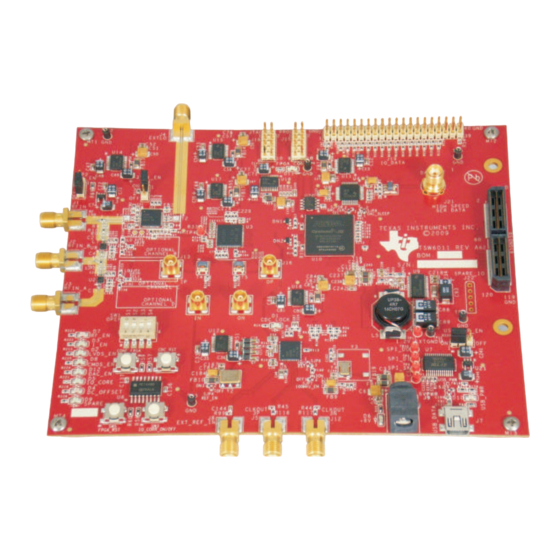
• Set sweep time to 2.5 ms • Set RBW to 300 kHz • Set VBW to 1 MHz Figure 3. TSW6011EVM Board Top View SLWU070B – February 2010 – Revised June 2010 TSW6011EVM Copyright © 2010, Texas Instruments Incorporated... -
Page 8: Software Operation
I_EXT Q_EXT Figure 4. TSW6011EVM Software GUI Front Panel To enable the GUI, the user must click on the button labeled Connect in the upper left-hand corner. If communication between the GUI and TSW6011 is successful, the button changes to display Disconnect. -
Page 9: Device Initialization
To issue a device reset, click on the Reset ADC button. • Click on the X in the upper right-hand corner to close the panel. SLWU070B – February 2010 – Revised June 2010 TSW6011EVM Copyright © 2010, Texas Instruments Incorporated... -
Page 10: Tr371125 Control Panel
Click on the BB Gain field and set the gain to 5. • Click the Filter Bypass checkbox to bypass the TR371125 LPF internal filter. TSW6011EVM SLWU070B – February 2010 – Revised June 2010 Copyright © 2010, Texas Instruments Incorporated... -
Page 11: Test Tone From Dac5672 Output
Board Bring Up www.ti.com After loading the TRF371125, the output spectrum now looks as shown in Figure Figure 8. Test Tone From DAC5672 Output SLWU070B – February 2010 – Revised June 2010 TSW6011EVM Copyright © 2010, Texas Instruments Incorporated... -
Page 12: Digital Processing Control Panel
IQ Correction Tap Shift Initial value is 13, which is coarse adaption. Users can choose the value of 18, Avg: which slows the adaption algorithm. TSW6011EVM SLWU070B – February 2010 – Revised June 2010 Copyright © 2010, Texas Instruments Incorporated... -
Page 13: Digital Processing Block Functions
Program ADC, PLL, and TRF371125 registers • Enable or disable the DC offset compensation algorithm • Set the LNA gain • Provide attenuation setting for TRF371125 SLWU070B – February 2010 – Revised June 2010 TSW6011EVM Copyright © 2010, Texas Instruments Incorporated... -
Page 14: Tr371125 Register Definitions
No adjustment of this register required ● Filter Trim No adjustment of this register required ● Out Buff Trim No adjustment of this register required TSW6011EVM SLWU070B – February 2010 – Revised June 2010 Copyright © 2010, Texas Instruments Incorporated... - Page 15 LVDS outputs. Mates with TSW1200 LVDS input connector. CMOS output data. Test connector. +6-VDC input power connector. USB connector. FPGA JTAG connector. FPGA PROM programming connector. SLWU070B – February 2010 – Revised June 2010 Copyright © 2010, Texas Instruments Incorporated...
- Page 16 USB connector. Spare dip switches. Currently not used. Turn I/Q correction on/off. Currently not used Not Used FPGA Reset. Reset all FPGA registers. CDC Reset SLWU070B – February 2010 – Revised June 2010 Copyright © 2010, Texas Instruments Incorporated...
- Page 17 ..................• Added D5: IQ correction enabled with blinking NOTE: Page numbers for previous revisions may differ from page numbers in the current version. SLWU070B – February 2010 – Revised June 2010 Revision History Copyright © 2010, Texas Instruments Incorporated...
- Page 18 Evaluation Board/Kit Important Notice Texas Instruments (TI) provides the enclosed product(s) under the following conditions: This evaluation board/kit is intended for use for ENGINEERING DEVELOPMENT, DEMONSTRATION, OR EVALUATION PURPOSES ONLY and is not considered by TI to be a finished end-product fit for general consumer use. Persons handling the product(s) must have electronics training and observe good engineering practice standards.
- Page 19 IMPORTANT NOTICE Texas Instruments Incorporated and its subsidiaries (TI) reserve the right to make corrections, modifications, enhancements, improvements, and other changes to its products and services at any time and to discontinue any product or service without notice. Customers should obtain the latest relevant information before placing orders and should verify that such information is current and complete.
Need help?
Do you have a question about the TSW6011EVM and is the answer not in the manual?
Questions and answers