Table of Contents
Advertisement
Quick Links
UM10699
User manual for SPI-bus RTC demoboard OM11059UL
Rev. 3 — 18 August 2020
Document information
Information
Content
Keywords
PCF85063BTL, OM11059UL, demoboard, how to get started, SPI-bus, RTC,
Real-Time Clock, tuning
Abstract
User manual for the RTC SPI-bus demoboard OM11059UL which contains
PCF85063BTL
User manual
Advertisement
Table of Contents

Related Manuals for NXP Semiconductors OM11059UL


Summary of Contents for NXP Semiconductors OM11059UL
- Page 1 User manual for SPI-bus RTC demoboard OM11059UL Rev. 3 — 18 August 2020 User manual Document information Information Content Keywords PCF85063BTL, OM11059UL, demoboard, how to get started, SPI-bus, RTC, Real-Time Clock, tuning Abstract User manual for the RTC SPI-bus demoboard OM11059UL which contains PCF85063BTL...
- Page 2 UM10699 NXP Semiconductors User manual for SPI-bus RTC demoboard OM11059UL Revision history Date Description 20200819 Added Section 6; changed "OM11059" to "OM11059UL" throughout 20150212 revised version 20130404 Initial version UM10699 All information provided in this document is subject to legal disclaimers.
-
Page 3: Introduction
The PCF85063x are a family of CMOS Real-Time Clocks (RTC) and calendar optimized for low power consumption. Different features sets are available. The OM11059UL is the ideal evaluation/demo board to use in the design phase of any project, just power and SPI-bus must be hooked up. -
Page 4: Hardware Set-Up
UM10699 NXP Semiconductors User manual for SPI-bus RTC demoboard OM11059UL Table 1. Block diagram of the PCF85063BTL RTC Hardware set-up 3.1 General requirements for the RTC PCF85063BTL The RTC circuit just requires one external part: a tuning fork quartz as resonator. - Page 5 UM10699 NXP Semiconductors User manual for SPI-bus RTC demoboard OM11059UL Table 2. Interfacing to microcontroller UM10699 All information provided in this document is subject to legal disclaimers. © NXP B.V. 2020. All rights reserved. User manual Rev. 3 — 18 August 2020...
-
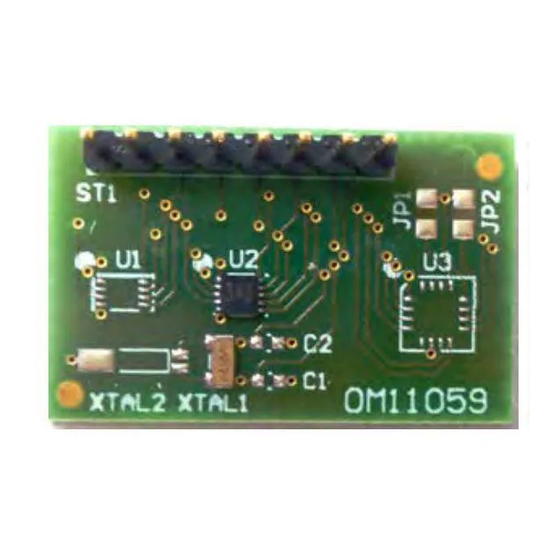
Page 6: Demo Board Om11059Ul
3.2 Demo board OM11059UL Table 3. Picture and layout of demo bard OM11059UL The OM11059UL allows to easily demonstrate operation of the PCF85063BTL with SPI- bus interface. No need to solder the tiny package to a breadboard 100 mil connector for straight forward connections. - Page 7 UM10699 NXP Semiconductors User manual for SPI-bus RTC demoboard OM11059UL There are quartzes on the market with different load capacitance C . 12.5 pF is most common, 7 pF offers however lower power consumption. By default a quartz with 7 pF is mounted.
-
Page 8: Software Set-Up
UM10699 NXP Semiconductors User manual for SPI-bus RTC demoboard OM11059UL Table 5. OM11059UL schematics Software set-up 4.1 Functionality The RTC PCF85063BTL is controlled via standard SPI-bus interface. Common SPI protocol applies. Theoretically there is no lower speed limit, however a read or write access to the RTC must be finalized within one second after initiating it, otherwise time counter increments could be lost. -
Page 9: System Testing
UM10699 NXP Semiconductors User manual for SPI-bus RTC demoboard OM11059UL 4.2 System testing There is a fast mode facility to test the functionality of the RTC; it can be activated by setting the EXT_TEST bit in the Control_1 word. The RTC PCF85063BTL has a frequency tuning facility; its operation is explained in section 5. -
Page 10: Rtc Tuning
UM10699 NXP Semiconductors User manual for SPI-bus RTC demoboard OM11059UL Name Address Setting Hours ..e.g. 03 (PM 03h) Days ..e.g. 14 (14th) Weekdays .. - Page 11 UM10699 NXP Semiconductors User manual for SPI-bus RTC demoboard OM11059UL Table 8. Temperature averaged over application range 5 °C to 45 °C 1. Characteristic if tuned to 32.768 kHz at 25 ºC. 2. Characteristic if tuned with the positive offset Δf UM10699 All information provided in this document is subject to legal disclaimers.
-
Page 12: Om11059Ul Board Fcc-Ce Emc Position
This documents NXP Semiconductors' position regarding the applicability of FCC and CE EMC requirements on the OM11059UL board. Applicability This document applies only to the OM11059UL board as defined by the documents in Agile for the Marketing PN OM11059UL. Product Description... - Page 13 UM10699 NXP Semiconductors User manual for SPI-bus RTC demoboard OM11059UL (2) Software developers to write software applications for use with the end product. This kit is not a finished product and when assembled may not be resold or otherwise marketed unless all required FCC equipment authorizations are first obtained.
-
Page 14: Legal Information
NXP Semiconductors products in order to avoid a modifications or additions. NXP Semiconductors does not give any... - Page 15 UM10699 NXP Semiconductors User manual for SPI-bus RTC demoboard OM11059UL Tables Tab. 1. Block diagram of the PCF85063BTL RTC ..4 Tab. 6. Setting the clock to 3.45 pm February 14, Tab. 2. Interfacing to microcontroller ......5 2015 ..............9 Tab.
-
Page 16: Table Of Contents
UM10699 NXP Semiconductors User manual for SPI-bus RTC demoboard OM11059UL Contents Introduction ............3 Key features ............3 PCF85063BTL ........... 3 Hardware set-up ..........4 General requirements PCF85063BTL ........... 4 Demo board OM11059UL ......... 6 Software set-up ........... 8 Functionality ............8 System testing ...........
Need help?
Do you have a question about the OM11059UL and is the answer not in the manual?
Questions and answers