Table of Contents
Advertisement
Quick Links
UM10300
User Manual OM6290 LCD Demo Board
Rev.1.0 — 8 August 2008
Document information
Info
Content
Keywords
LCD driver, segment driver, character driver, graphic driver, PCF8576D,
PCF2119, PCF8531, PCA9633, ARM7, LPC2148, battery powered, USB
Abstract
The OM6290 is a LCD driver evaluation board which can be used to
demonstrate and evaluate three different types of LCD drivers: The
PCF8576D is a segment driver, the PCF2119 a character driver and the
PCF8531 a dot matrix driver. The NXP family of LCD drivers consists of
these three different types, with several type numbers for each type.
From an application point of view, the type numbers within one type
family are very similar and also software can be easily adapted.
The board provides a starting point for applications using an NXP LCD
driver, both from the hardware and software point of view.
User manual
Advertisement
Table of Contents

Related Manuals for NXP Semiconductors OM6290


Summary of Contents for NXP Semiconductors OM6290
- Page 1 PCF2119, PCF8531, PCA9633, ARM7, LPC2148, battery powered, USB Abstract The OM6290 is a LCD driver evaluation board which can be used to demonstrate and evaluate three different types of LCD drivers: The PCF8576D is a segment driver, the PCF2119 a character driver and the PCF8531 a dot matrix driver.
- Page 2 UM10300 NXP Semiconductors User Manual OM6290 Revision history Date Description 20080808 Initial version Contact information For additional information, please visit: http://www.nxp.com For sales office addresses, please send an email to: salesaddresses@nxp.com UM10300_1 © NXP B.V. 2008. All rights reserved. User manual Rev 1.0 —...
-
Page 3: Contents
User Manual OM6290 1. Introduction This User Manual describes the OM6290 LCD Demo board. This board was developed in order to provide a tool for application engineers and development engineers wishing to try and evaluate the possibilities of some of our LCD driver IC’s and to get hands-on experience with writing code for these drivers. -
Page 4: Board Description And Layout
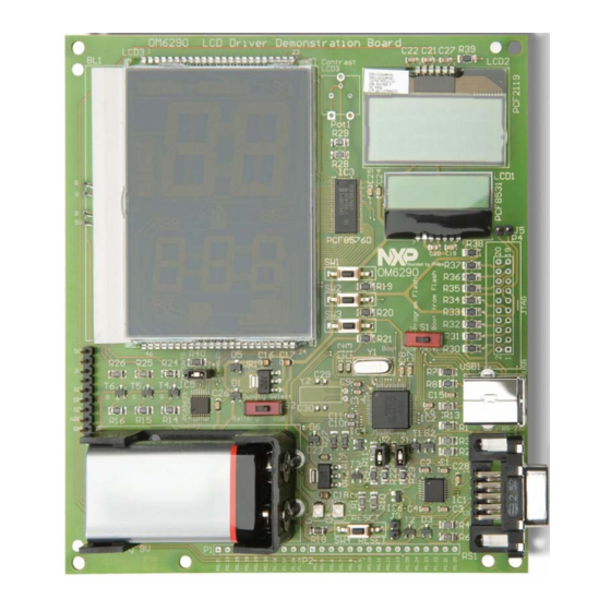
UM10300 NXP Semiconductors User Manual OM6290 2. Board description and layout Below the top view of the board is given. LCD3 is the large display on the left. For this display a backlight is used which is controlled by the PCA9633 LED driver. On the top right LCD2 is present and the smaller display below LCD2 is LCD1. -
Page 5: Switches
LPC2148 boot from its internal flash. The OM6290 is a USB-powered device. Alternatively the board can be powered using a standard 9V (6LR61 / PP3) battery. A battery holder is present on the board and switch S2, located between the battery holder and LCD3, can be used to select either USB- power or battery power. -
Page 6: Connectors
UM10300 NXP Semiconductors User Manual OM6290 2.4 Connectors On the left below LCD3 a pin strip P3 is available which carries the following signals: 5V, 3V3, SCL, GND, SDA and nRES. The latter is connected to the reset circuit IC6 and by making nRES LOW, a defined reset signal is generated. -
Page 7: Hardware Requirements
User Manual OM6290 2.6 Hardware requirements In order to be able to modify the firmware of the OM6290 Demo Board you need: • The OM6290 Demo Board • An IBM-compatible PC with an unused USB port to supply power to the board (alternatively via a battery) and an unused RS232 COM port for Flash In-System Programming (ISP) via the Serial Interface. -
Page 8: The Lcd Drivers
UM10300 NXP Semiconductors User Manual OM6290 LCD1 shows three lines of text, with in the right bottom corner the version number. Upon pressing any of the switches SW1, SW2 or SW3 the backlight of LCD3 turns on. LCD1. Power on: The NXP logo is displayed. Starting from v1.1, the following text is displayed over three lines,: “NXP founded by Philips”... -
Page 9: Segment Driver Pcf8576D
UM10300 NXP Semiconductors User Manual OM6290 • Resolutions that are not common in the market: 34 x 128, 65 x 133, 80 x 128. 3.1 Segment Driver PCF8576D 3.1.1 General Description The PCF8576D is a peripheral device which interfaces to almost any Liquid Crystal Display (LCD) with low multiplex rates. -
Page 10: Block Diagram
UM10300 NXP Semiconductors User Manual OM6290 manufactured in silicon gate CMOS process AEC-Q100 compliant (TQFP64). 3.1.3 Block diagram S0 to S39 BP2 BP1 BP3 4 to 43 BACKPLANE DISPLAY SEGMENT OUTPUTS OUTPUTS DISPLAY REGISTER VOLTAGE SELECTOR OUTPUT BANK SELECT DISPLAY... -
Page 11: Features
UM10300 NXP Semiconductors User Manual OM6290 3.2.2 Features Single-chip LCD controller/driver 2-line display of up to 16 characters + 160 icons, or 1-line display of up to 32 characters + 160 icons 5 x 7 character format plus cursor; 5 x 8 for kana (Japanese) and user defined... -
Page 12: Block Diagram
UM10300 NXP Semiconductors User Manual OM6290 3.2.3 Block diagram C1 to C80 R17DUP R1 to R18 60 to 99, 51 to 59, 101 to 140 141 to 149 COLUMN DRIVERS ROW DRIVERS BIAS 44 to 49 VOLTAGE LCD1 GENERATOR DATA LATCHES... -
Page 13: Features
UM10300 NXP Semiconductors User Manual OM6290 voltages, resulting in a minimum of external components and low power consumption. The PCF8531 is compatible with most microcontrollers and communicates via a two-line bidirectional bus (I C-bus). All inputs are CMOS compatible. Similar devices are PCF8535 (65 rows x 133 columns) and PCF8811 (80 rows x 128 columns). -
Page 14: Block Diagram
UM10300 NXP Semiconductors User Manual OM6290 3.3.3 Block diagram R0 to R33 C0 to C127 COLUMN DRIVERS DRIVERS POWER-ON RESET INTERNAL PCF8531 RESET DATA LATCHES OSCILLATOR BIAS MATRIX VOLTAGE LCDIN LATCHES GENERATOR TIMING GENERATOR DISPLAY DATA RAM LCDSENSE DISPLAY MATRIX DATA... -
Page 15: Using Μvision And Flashmagic
UM10300 NXP Semiconductors User Manual OM6290 Features include: 60-MHz, 32-bit ARM7TDMI-S with AHB/APB interfaces 512 KB of ISP/IAP Flash 40 KB of SRAM Very fast Flash programming via on-chip boot loader USB 2.0 full-speed (12 Mbps) device Two 10-bit A/D converters, providing 14 analog inputs... - Page 16 UM10300 NXP Semiconductors User Manual OM6290 • The RealView Linker does not accept scatter-loading description files for sophisticated memory layouts; • The RealView Linker restricts the base address for code/constants to 0xXX000000, 0xXX800000, or 0x00080000 where XX is 00, 01, ..., FF. This allows memory start addresses like 0x00000000 and 0x12800000;...
-
Page 17: Installing Μvision
To create a new project to run on the LCD Eval Board, select The IDE has to be configured for the microcontroller used on the OM6290 board. In order to do so, select “Project” -> “New μVision Project” and enter a project name, after which a window similar to that indicated in Fig 6 pops up. - Page 18 In order to achieve this, select Project -> Options for Target ‘OM6290’. The window below pops up. Set the Xtal frequency to 12 MHz. The ARM7 CPU is capable of executing two instruction sets; the ARM instruction set which is 32 bits wide or the Thumb instruction set which is 16 bits wide.
-
Page 19: Selection Of The Toolset
Fig 8. Linker options 5.1.3 Selection of the toolset The downloaded demoboard firmware contains the file ‘OM6290 Demoboard.Uv2’ which is the project configuration file. All settings are correct. In case settings are made manually the information provided here is useful. -
Page 20: The Flashmagic Utility
UM10300 NXP Semiconductors User Manual OM6290 The toolset to be used can be selected in the μVision IDE under Project -> Manage -> Components, Environment, Books. This is indicated in Fig 9. Fig 9. Selection of tool set 5.2 The FlashMagic Utility NXP has partnered with Embedded Systems Academy to provide a free tool for flash programming called FlashMagic. - Page 21 UM10300 NXP Semiconductors User Manual OM6290 • Program security bits; • Check which Flash blocks are blank or in use with the ability to easily erase all blocks in use; • Read the device signature; • Read any section of Flash and save as an Intel Hex File;...
- Page 22 UM10300 NXP Semiconductors User Manual OM6290 In Fig 10 a screenshot of Flash Magic (with correct settings, version 3.59) is given. Fig 10. Screenshot Flash Magic Remark: Some boards were programmed with code compiled using CARM compiler. If the code compiles using RealView but does not run after programming the LPC2148, checking the option ‘Erase all Flash+Code Rd Prot’...
-
Page 23: Quick Start
User Manual OM6290 6. Flash Magic Quick Start Setting up the OM6290 board is easy and explanations for the board setup are given here. In stand-alone mode only a 9V battery is used to provide power to the board and let the onboard program run. -
Page 24: Software Description
UM10300 NXP Semiconductors User Manual OM6290 b. Verify the COM connection using the menu command ISP – Read Device Signature c. The Read Device Signature window pops up as below Fig 12. Device signature read Click on Close to close the window. If this all works, the COM port communicates with the onboard controller. -
Page 25: Technical Data
UM10300 NXP Semiconductors User Manual OM6290 9. Technical Data Table 1. Technical Data Short summary of Technical Data, indicative values only Parameter Value Remark Supply Voltage +5V via USB Supply current via USB is about 5 mA less than via battery supply. -
Page 26: Partslist
UM10300 NXP Semiconductors User Manual OM6290 11. Parts List Below the parts list of the board is given. Table 3. Component list (BOM) Bill of Material Main category Designator Type / value Description Footprint Passives R17, R27 33 Ω resistor... - Page 27 UM10300 NXP Semiconductors User Manual OM6290 Main category Designator Type / value Description Footprint Rakon LF A158K Crystal 12 MHz Semiconductors MAX3232ECAE+ RS-232 transceiver SSOP16 LPC2148FBD64 Micro controller LQFP64 / SOT314-2 PCF8576DT/2 Segment driver TSSOP56 / SOT364-1 PRTR5V0U2AX ESD protection...
-
Page 28: References
UM10300 NXP Semiconductors User Manual OM6290 12. References The documents listed below provide further useful information. They are available on the CD but the latest versions can be downloaded from NXP’s website www.nxp.com or on www.standardics.nxp.com. 1. Product data sheet PCF8576D;... -
Page 29: Legal Information
Notice: All referenced brands, product names, service names and trademarks are property of their respective owners. Right to make changes — NXP Semiconductors reserves the right to make changes to information published in this document, including without <Name> — is a trademark of NXP B.V. -
Page 30: Table Of Contents
UM10300 NXP Semiconductors User Manual OM6290 14. Contents Introduction ............3 The onboard microcontroller......14 Board description and layout......4 Using µVision and FlashMagic ......15 Switches.............5 Keil µVision ............15 LED indicators............5 5.1.1 Installing μVision ..........17 Jumpers .............5 5.1.2 Selection of the microcontroller ......17 Connectors............6...
Need help?
Do you have a question about the OM6290 and is the answer not in the manual?
Questions and answers