Advertisement
Quick Links
LUXOMAT
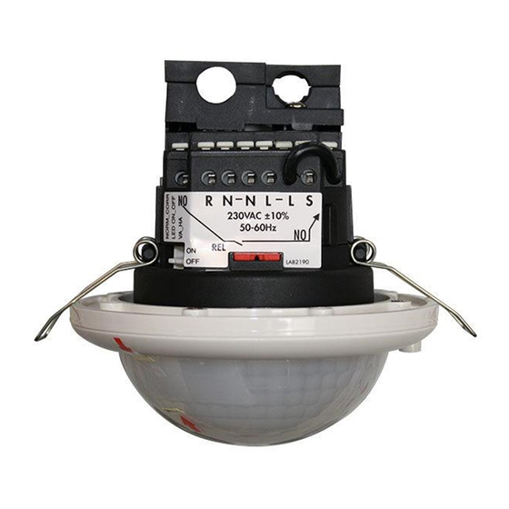
Installation and Operating Instruction for B.E.G. Occupancy detector PD4-M-1C-C-PS-SM/FC
1. Mounting preparation
Work on the 230 V mains supply may only be carried out
by qualified professionals or by instructed persons under
the direction and supervision of qualified skilled electrical
personnel in accordance with electredechnical regulations.
Disconnect supply before installing!
The device is not suited for safe disconnection of the mains
supply.
When in Master/Slave mode of operation, the Master-
appliance must always be installed at the location where
there is least daylight.
4a. Installation of the LUXOMAT
®
1C-C-PS-SM
ATTeNTION: For maximum
sensitivity the detector-,
lens- and corridor-axis must
match.
opened
C
open
close
The detector must be in stalled on a solid and level
surface. The circular cover ring must be removed prior
to assembly. To do this, twist the lens (C) anticlockwise
through approximately 5° and lift off.
Having connected up the wires in accordance with
regulations, secure the detector with 2 screws. After
installation replace the lens and lock (turn clockwise).
Mains to be connected.
4b. Installation of the LUXOMAT
®
C-PS-FC
A circular opening of
diameter 68 mm must
first of all be produced
in the ceiling.
Having connected up
the cables in accord-
ance with regulations,
the detector is inserted
into the opening as
shown in the drawing
opposite and fixed into
position with the assis-
tance of the spring clip.
ATTeNTION: For maximum sensitivity the detector-, lens-
and corridor-axis must match.
7. DIP-switch functions
DIP-
ON
OFF
switch
1
Semi automatic mode
Fully automatic mode
2
LED OFF
LED ON
3
Corridor mode
Standard mode
All manuals and user guides at all-guides.com
PD4-M-1C-C-PS
®
2. Operation of the PD4-M-1C-C-SP
For an increased operational safety the PD4-M-C-FC-SP is
fitted with two relays:
Relay 1 = operating relay with NO-contact
Relay 2 = fault relay with NC-contact
A number of basic functions are monitored in the device and
in case of a deviation a failure is shown. Blinking of all LEDs
indicates a recognized failure.
In this position the NC relay has fallen off and is responsible
for the contact between L and L' (light on). A recognised
failure can only be reset by a network interruption!
PD4-M-
5a. Hardware configuration SM
Position LED's and potentiometers
closed
LED 1 green
LED 2 red
LED 3 white
PD4-M-1C-
5b. Hardware configuration FC
Position LED's and potentiometers
LED 1 green
LED 2 white
LED 3 red
OFF
ON
1
DIP
2
3
Potentiometer 1 Lux
Potentiometer 2 Time
1 2
3
40
1
2 3
1
2
Potentiometer 1 Lux
Potentiometer 2 Time
Corridor function: After deactivation by an external push
button, the detector switches off and returns to automatic
mode after 5 sec.
The DIP settings are enabled again by:
• Adjusting the DIP-switches when closed
• Reset with test sun setting at the potentiometers
• Reset when open
3. Monitored functions
Tension monitoring
Operating tension is monitored internally. If a voltage failure is
recognized, a failure is activated.
CdS-monitoring
Monitoring if the detector switches between the positions light /
dark (active / not active) within a period of 24 hours. If the
appliance did not change the position "too light" within this
period of time, the light sensor is defective (or wrong program-
ming) and a failure is activated.
Relay monitoring
When switched on, a phase monitoring of L' is active. If not
recognized, the relay or the contact is defective and a failure is
activated.
6a. Position DIP-switches SM
1
2
40
OFF
ON
Surface
VA
LED
mounting
DIP 1
Fully-automatic/semi-automatic mode
DIP 2
LED ON/OFF
DIP 3
Change between corridor mode and standard
mode
The DIP-switch settings are
using the remote control.
overriden
6b. Position DIP-switches FC
1
False ceiling
mounting
DIP 1
Fully-automatic/semi-automatic mode
DIP 2
LED ON/OFF
DIP 3
Change between corridor mode and standard
mode
The DIP-switch settings are
overriden
using the remote control.
GB
3
OFF
ON
HA
DIP
COR
2
3
DIP
OFF
ON
Advertisement

Related Manuals for B.E.G. LUXOMAT PD4-M-1C-C-PS


Summary of Contents for B.E.G. LUXOMAT PD4-M-1C-C-PS
- Page 1 All manuals and user guides at all-guides.com PD4-M-1C-C-PS LUXOMAT ® Installation and Operating Instruction for B.E.G. Occupancy detector PD4-M-1C-C-PS-SM/FC 2. Operation of the PD4-M-1C-C-SP 3. Monitored functions 1. Mounting preparation For an increased operational safety the PD4-M-C-FC-SP is Tension monitoring Work on the 230 V mains supply may only be carried out fitted with two relays: Operating tension is monitored internally.
- Page 2 120 60 50 16 10 9. Reset and default settings Option: Remote control IR-PD-1C (92520) 8. Putting into operation / Settings All manuals and user guides at all-guides.com 16 10 (Label to be used with IR-PD) TEST Self test cycle 1.
- Page 3 14. Switch-off threshold brightness 17. Fully-automatic and semi-automatic mode 20. Technical data PD4-Master-1C-C-SP All manuals and user guides at all-guides.com (see functions IR-PD-1C) 1. If the switch-on threshold has been modified by the potentiometer Sensor and power supply in one case or remote control, the switch-off threshold stored in the EEPROM is ON/OFF Power supply:...
- Page 4 23a. PD4-M-1C-C-PS-SM – Connection 24. LED function displays All manuals and user guides at all-guides.com Wiring Diagram LeD function indicators after each mains recovery (60 sec. initialisation period) PD4-M-1C-C-PS-SM Operating state LeD function indicators Factory pro- White, red and green flash in quick succession for 10 sec., then initialisation indicators, gram active see below Double-locked...
Need help?
Do you have a question about the LUXOMAT PD4-M-1C-C-PS and is the answer not in the manual?
Questions and answers