Table of Contents
Advertisement
Quick Links
LUXOMAT
Installation and Operating Instruction for B.E.G. – Occupancy detector PD4-M-2C-DS-FC
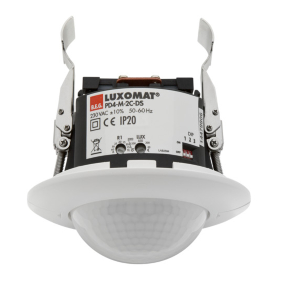
1. Product information
For an increased reliability of the
illumination system the PD4-M-
2C-DS can be connected to two
seperate ciruits of the alternating
current network.
Thus, the illumination system can
be divided into two electrically
isolated groups, thereby reducing
the risk of total failure of the il-
lumination system importantly.
The convenience of a shared
pushbutton for both groups is
preserved based on the fact that
the pushbutton is also electrically
isolated.
5. Hardware configuration
Position Potentiometer and DIP-switch
DIP1 VA/HA
Potentiometer 1 Lux
DIP2 Master/Slave
Potentiometer 2 Time
DIP3 Corridor mode/standard mode
3
2
1
R
S
L
L
DIP
Rel1
230 VAC ±10%
OFF
DIP
50-60 Hz
2
321
ON
The DIP switch settings are overriden using the remote
control.
7. Putting into operation / Settings
Self test cycle
After an initial 60-second self-test cycle, the LUXOMAT
PD4-M-2C-DS is ready for operation.
Potentiometer 1 - Adjustment follow-up time
R1
"Light"
20
15
30s
15s
Symbol TEST: Test mode, reacts on motion
TE
only. Every movement switches on the light
for a period of 2 seconds, switching it off for
a period of 2 seconds. The time can be set
infinitely variably at between 15 sec. and 60
minutes.
Potentiometer 2 - Adjustment twilight-switch
LUX
The switch-on value for the light can be set
at between 10 and 2000 Lux. Using the
potentiometer, the luminance set points can be
set as desired.
Symbol :
Night operation
Symbol
:
Day/Night operation
Determining the current brightness
Set potentiometer 1 to the "Test" setting. The
green LED lights up permanently as soon as the
value set at the potentiometer 2 exceeds the
current measured brightness.
The potentiometer settings are valid for both switching chan-
nels. They are overriden using the remote control.
®
2. Safety note
Work on the 230 V mains supply may only
!
be carried out by qualified professionals or
by instructed persons under the direction
and supervision of qualified skilled electrical
personnel in accordance with electrotechnical
regulations.
Disconnect supply before installing!
!
The device is not suited for safe disconnection
!
of the mains supply.
Attention:
!
Both the switch push buttons and the (-) - and
(+) - clamps must not be connected to the
supply voltage! The pushbutton is supplied
directly from the device.
6. DIP switch functions
DIP-
switch
1
2
3
Rel2
N
1
Slave function
When using the detector as slave device it sends a data
telegram to the master device upon each detection of mo-
tion, disregarding ambient luminosity.
8. Reset and default settings
®
1
R1
20
15
30s
15s
TE
2. Reset
If both potentiometers are returned to the "Test" and "Sun"
setting from any other position, a reset is executed. All values
programmed with the remote control are deleted.
9. Putting into operation of the remote
control IR-PD-1C (optional)
Check Battery:
Open battery compartment by pressing the
plastic springs together and removing the
battery-holder.
Caution: Settings with remote control supersede the
settings by potentiometers.
PD4-M-2C-DS
3. Installation of the PD4-M-2C-DS
100 mm
ON
OFF
Semi automatic mode
Fully automatic mode
Slave
Master
Corridor mode
Standard mode
1. Default settings
If the potentiometers are in the
2
"Test" and "Sun" position and
LUX
the detector is unprogrammed,
the factory program is acti-
vated: 500 lux and 10 min.
4. Hardware configuration
A circular opening of diameter
100 mm must first of all be
produced in the ceiling.
Having connected up the ca-
bles in accordance with regula-
tions, the detector is inserted
into the opening as shown in
the drawing opposite and fixed
into position with the assistance
of the spring clip.
When in Master/Slave mode
1 LED red
of operation, the Master-appli-
2 LED green
ance must always be installed
3 LED white
at the location where there is
least daylight.
OFF
1
DIP
2
3
Corridor function:
After deactivation by an external push button, the
detector switches off and returns to automatic mode after 5 sec.
The DIP settings are enabled again by:
• Adjusting the DIP switches when closed
• Reset with test sun setting at the potentiometers
• Reset when open
Semi automatic mode/Fully automatic mode: see pt. 16
Option: Remote control IR-PD-1C
B.E.G.
B.E.G.
B.E.G.
LUXOMAT
Wall bracket for remote control IR-PD-1C
By means of this remote control all settings of
the presence detector can be made comfort-
ably from the ground. A useful wall bracket is
included in delivery.
GB
80 - 90 mm
Position LED's
3
2
1
ON
LUXOMAT
LUXOMAT
®
®
IR-PD-1C
PD3
®
500
400
200
100
20
HA
ON/OFF
PIR
CdS
Advertisement
Table of Contents

Subscribe to Our Youtube Channel
Related Manuals for B.E.G. LUXOMAT PD4-M-2C-DS


Summary of Contents for B.E.G. LUXOMAT PD4-M-2C-DS
- Page 1 PD4-M-2C-DS LUXOMAT ® Installation and Operating Instruction for B.E.G. – Occupancy detector PD4-M-2C-DS-FC 80 - 90 mm 4. Hardware configuration 1. Product information 2. Safety note 3. Installation of the PD4-M-2C-DS Position LED’s 100 mm A circular opening of diameter For an increased reliability of the Work on the 230 V mains supply may only 100 mm must first of all be...
- Page 2 10. Settings with remote control IR-PD-1C in opened state 11. Key functions in closed state Unlocking device - Activation of the programming mode Permanent protection against sabotage Daytime operation, detector only This function blocks the unit perma- activated by motion nently.
- Page 3 17. Range of Coverage 15. Other functions 16. Fully automatic and semi automatic mode (see functions IR-PD-1C) Activation of light for 12 h via mains interruption ON/OFF Fully automatic operation 2,50 m 1. Interrupt current of both supply lines In this operating mode, the lighting switches automatically 2.
- Page 4 23. PD4-M-2C-DS-FC - Connection 24. LED function indicators in master-configuration (default) LED function indicators after each mains recovery (60 sec. initialisation period) Operating state LED function indicators Factory program White, red and green flash in quick succession for 10 sec., then initialisation indicators, Slave active see below...
Need help?
Do you have a question about the LUXOMAT PD4-M-2C-DS and is the answer not in the manual?
Questions and answers