Table of Contents
Advertisement
Advertisement
Table of Contents

Related Manuals for B.E.G. LUXOMAT BL2


Summary of Contents for B.E.G. LUXOMAT BL2
- Page 1 Motion detector Operating Manual 93317...
- Page 2 All device data can also be found here: https://www.beg-luxomat.com/qr.php?prtno=93317 © 2019 B.E.G. Brück Electronic GmbH Gerberstraße 33 51789 Lindlar GERMANY Phone: +49 (0) 2266 90121-0 Fax: +49 (0) 2266 90121-50 E-mail: info@beg.de Internet: beg-luxomat.com...
-
Page 3: Table Of Contents
Content About this document ............3 1.1 Other applicable documents . - Page 4 Content Commissioning ............14 6.1 Factory default settings .
-
Page 5: About This Document
93317 About this document Other applicable documents Short operating manual MAN_9728_120717-1 (supplied with the device). Used symbols and signal words Symbol indicating possible dangers to persons Symbol indicating possible property damage Symbol for useful information and tips NOTICE Signal word for possible property damage CAUTION Signal word for possible minor injuries WARNING... -
Page 6: Foreseeable Misuse
93317 Foreseeable misuse Any use other than that defined under "Intended use" or which goes beyond that use is considered improper use. In particular, use of the device is not permitted in the following cases: ■ in rooms with explosive atmospheres ■... -
Page 7: Device Description
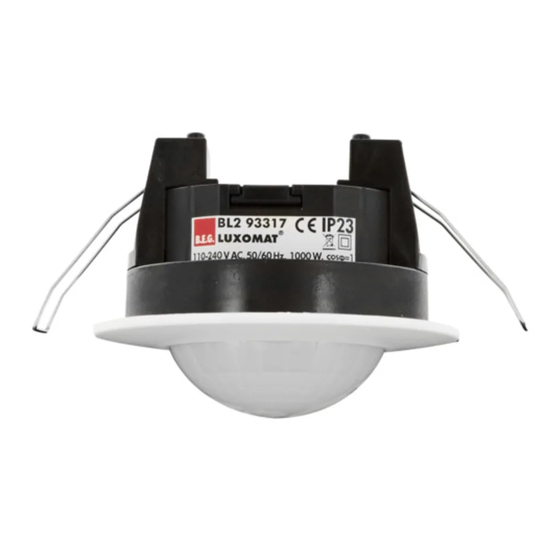
93317 Device description Device overview 1 Spring clamps for ceiling installation (removable) 2 Lens 3 Wiring compartment with cover The device is a motion detector for ceiling mounting having a circular detection area. Settings can be made with the IR-BL infrared remote control. Operating Manual... -
Page 8: Functions
93317 Functions The general operation of the motion detector is described in the short operating instructions supplied with the device. Passive infrared motion detectors register movements of heat sources and convert them into signals that are evaluated by a processor. The device is a switching detector. -
Page 9: Mounting
93317 Mounting Choice of mounting location The most important aspect of motion detection is the correct choice of mounting location. ➜ Mount the detector so that the main direction of movement is always tangential (transverse to the device). ➜ Always mount the detector at the location with the lowest amount of daylight. If the smallest movements are to be detected (e.g. -
Page 10: Mounting Options
93317 Mounting options 4.2.1 Ceiling installation Ø 68 mm 4.2.2 Surface mounting with mounting set 93256 Operating Manual... - Page 11 93317 Operating Manual...
-
Page 12: Flush Mounting With Mounting Set 93251
93317 4.2.3 Flush mounting with mounting set 93251 Operating Manual... -
Page 13: Electrical Connection
93317 Electrical connection DANGER Danger of death due to electrical shock! Work on electrical equipment may only be carried out by certified electricians or by instructed persons under the direction and supervision of a certified electrician in accord- ance with the electrical engineering regulations. ➜... -
Page 14: Preparing The Connection
93317 Preparing the connection 5.1.1 Preparing the connection cable 0.5 … 1.5 mm 10mm 0.5 … 1.5 mm 1 Solid conductors 2 Stranded conductors 3 Stranded conductors with ferrules 5.1.2 Opening the terminal compartment. 5.1.3 Strain relief/protection against accidental contact NOTICE Install strain relief/protection against accidental contact! The cover of the terminal compartment also serves as strain relief and protection against... -
Page 15: Schematic Wiring Diagrams
93317 Schematic wiring diagrams 5.2.1 Standard connection 1 Switch for manual switching RC suppressor for arc extinction (accessory, optional) 5.2.2 Parallel connection NOTICE Parallel connection! Up to 8 detectors can be connected in parallel to extend the detection range. . ➜... -
Page 16: Rc Suppressor Unit
93317 RC suppressor unit NOTICE Interference suppression of the loads! All switched loads must be properly suppressed. We recommend our RC suppressor units (see accessories). Commissioning Factory default settings The values printed in bold are the factory settings. Device 500 Lux Switch-on threshold Adjustment range by remote control: 20 Lux - 1000 Lux... -
Page 17: Adjustment Via Ir Remote Control
93317 Adjustment via IR remote control 93055 – IR-BL The device can be adjusted by infrared remote control. No adjustments can be made to the device itself. The white LED of the detector flashes briefly fast to confirm the correct reception of an IR signal. 6.3.1 Commands Button... -
Page 18: Parameter
93317 6.3.2 Parameter Button Parameter Day operation The switching of the output when a movement is detected is almost light-independent (switch-on threshold approx. 2000 lux). Night operation The light evaluation is performed with a minimum switch-on threshold of 10 lux. Switch-on threshold The brightness value below which the illumination is switched on is called the switch- on threshold. -
Page 19: Adjusting The Parameters With The Remote Control
93317 6.3.3 Adjusting the parameters with the remote control Open (unlock) the device – Activate the programming mode Day operation (light evaluation inac- tive) or Night operation Select switch-on threshold or read in current light value as new switch-on threshold. Follow-up time (illumination) 15 s –... -
Page 20: Care, Maintenance And Disposal
93317 Care, maintenance and disposal Cleaning If necessary, clean the plastic lens of the motion detector with a soft, lint-free cloth. NOTICE Do not use aggressive cleaning agents! ➜ Do not use aggressive cleaning agents such as thinner or acetone for cleaning the device. -
Page 21: Diagnostics And Troubleshooting
93317 Diagnostics and troubleshooting The connected luminaire does not switch ■ The luminaire is defective: ➜ Replace luminaire/lamp ■ No mains voltage available: ➜ Check the fuse in the subdistribution ■ The turn-on threshold is not set correctly: ➜ Correct threshold ■... -
Page 22: Service And Support
93317 Service and support Manufacturer's warranty The company B.E.G. Brück Electronic GmbH grants a warranty in accordance with the warranty conditions, which you can download from the website at https://www.beg-luxomat.com/service/ downloads/ . 9.1.1 Product code The product is provided with a product code that enables the product to be traced in the event of a warranty/complaint. -
Page 23: Technical Data
93317 Technical Data 10.1 General data Voltage AC 110 – 240 V , 50/60 Hz Power consumption approx. 0.3 W Terminal clamps 0.5 – 1.5 mm , for solid one-wire conductors Connection cable (recommended) NYM 5 x 1.5 mm Circuit breaker max. -
Page 24: Dimensioned Drawings
93317 10.2 Dimensioned drawings 10.2.1 Ceiling installation 10.2.2 Surface mounting with mounting set 93256 Ø Ø Ø 12 max. 19,5 M 1:2 Operating Manual... -
Page 25: Flush Mounting With Mounting Set 93251
93317 10.2.3 Flush mounting with mounting set 93251 10.2.4 Wire basket BSK 92199 Ø Ø Ø Operating Manual... -
Page 26: Accessories / Ordering Information
93317 Accessories / Ordering information Art. No. Designation 93055 Remote control IR-BL 93256 Mounting set surface-mounted 93251 Mounting set flush-mounted 10880 RC suppressor unit 10882 Mini RC suppressor unit 92199 Wire basket / white EU declaration of conformity The product complies with the following EU directives Electromagnetic Compatibility (2014/30/EU) Low voltage (2014/35/EU) Restriction of the use of certain hazardous substances in electrical and electronic equipment...
Need help?
Do you have a question about the LUXOMAT BL2 and is the answer not in the manual?
Questions and answers