Table of Contents
Advertisement
Quick Links
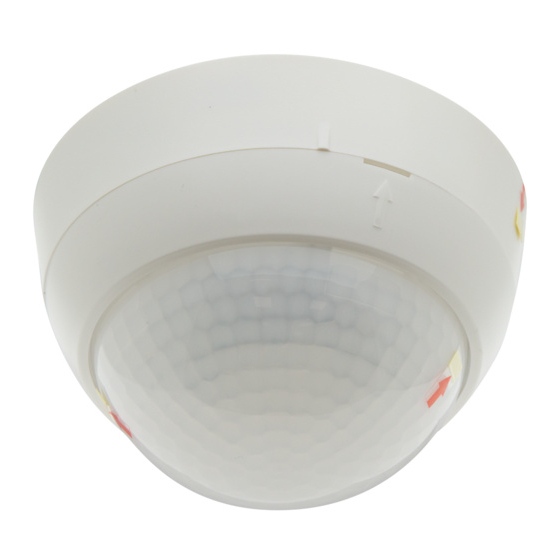
PD4-M-1C-GH-SM
B.E.G.
Installation and Operating Instruction for B.E.G. Controls - Occupancy sensor PD4-M-1C-GH-SM
1. Product information
• Occupancy detector designed for high-bay warehouses
• One potential-free (dry) contact
• Version as Master device
• Detection area can be extended with Slave devices
• Manual switching via pushbutton possible
• Simple operation with remote control (required)
• Factory settings 3 min and 1000 lux
2. Operation
The occupancy detector controls the light automatically according
to people present (movements) and the ambient brightness.
The integrated light sensor constantly measures the ambient light
and compares it with the switch-on threshold set in the detector. If
the ambient light is sufficient, lighting will not be switched on. If
the ambient light level is below the brightness level, a movement
activates the lighting in the room.
The detector switch the light off, if there is enough natural light for
15 min. or until the follow-up time do not recognized any move-
ment in the room.
3. Safety information
Work on the mains supply may only be carried out
!
by qualified professionals or by instructed persons
under the direction and supervision of qualified skilled
electrical personnel in accordance with electrical
regulations.
!
Disconnect supply before installing!
This device is not to be used to isolate other equipment
!
from the mains supply.
The total number of switchable loads is limited due
!
to high inrush currents of electronic ballasts and LED
drivers. In case of a large number of connected loads
please use an external contactor
For all connected loads, proper interference sup-
!
pression is obligatory (we recommend to use our arc
extinction kits).
4. Installation of the PD4-M-1C-GH-SM
C
The detector must be in stalled on a solid and
level surface. The circular cover ring must be
open
close
removed prior to assembly. To do this, twist the
lens (C) anticlockwise through approximately
5° and lift off.
Having connected up the wires in accordance
with regulations, secure the detector with 2
screws.
After installation replace the lens and lock (turn
clockwise). Mains to be connected.
ATTENTION: Install the unit in such a manner
that both markings on the housing are posi-
tioned in the longitudinal axis of the area to be
monitored (e.g. high-bay corridors).
When used in high-bay warehouses,
care should be taken that, in the cross-
aisles of the warehouse, detectors are
installed that can detect movement only
in the desired aisle locations, by using
blinds or other technical arrangements.
5. Self-test cycle
The product enters an initial 60-second self-test cycle, when the
supply is first connecteded. The occupancy detector is ready for
operation.
During the self-test cycle, the following settings can be made:
Light stop active: (A)
Corridor function active (only via button
(see 8.)
6. Putting into operation / Settings
Factory settings
The PD4-M-1C-GH-SM is preset with time setting 5 min. and
switch-on threshold 1000 Lux.
Attention:
No potentiometer settings are possible on the device. Changes
to the settings can only be made by using B.E.G. Controls IR
adapter for smartphones resp. remote control app.
7. Fully / Semi automatic mode
Full automatic operation
In this operating mode, the lighting switches automatically on
and off for increased comfort, depending on presence and
brightness.
Semi-automatic operation
(Semi-automatic can only be activated by remote control!)
In this operating condition, in order to gain increased savings,
the lighting is energized only after being manually switched on.
Switch-off takes place automatically.
The semi-automatic mode basically behaves like the full automatic
one.
The channels can be switched back on automatically if there is
movement in the 10 seconds after the end of the follow-up time.
After this time has elapsed, the respective push button must be
pressed to switch on the channels.
8. Manual Switching
(A) To switch the light on and off, press the button briefly. The
light remains switched on or off for as long as people are
detected plus the set lag time.
(B) If the "Corridor" function was activated in the selftest cycle,
the light remains off for 5 seconds after shutdown (red and green
LEDs flash). Then the automatic function is active again.
9. Wiring diagram
Schematic diagram – when connecting the detector, please
respect the labelling of the terminal connections at the detector!
Standard mode with Master 1-channel occupancy
detectors (NO) with R and S terminal
L
N
PB1
Optional
T1 = NO-button for semi automatic mode; Extension of the detec-
tion area with Slave devices
10. Range of Coverage
Walking across
1
Walking towards
2
11. Range in relation to mounting height
Range (oval detection) (walking towards)
Mounting height
): (B)
H
5.0 m
6.0 m
7.0 m
8.0 m
14.0 m
E1
S
N
L
NO
NO
R
R
C1
Master
Slave
1
in longitudinal
90° to longitudi-
axis (L)
nal axis (B)
26.0 m
18.0 m
26.0 m
18.0 m
28.0 m
19.0 m
28.0 m
19.0 m
30.0 m
19.0 m
HA
OFF
HA
ON
12. Exclude sources of interference
SM
If the detection zone is too large or areas are covered that should not
be monitored, use the blinds to reduce or limit those areas.
13. Technical data
Sensor and power supply in one
Power supply:
Power consumption:
Ambient temperature:
Protection degree/class:
Settings:
Switch-on threshold IR-PD-LD: 10 - 2000 Lux
Detection area:
Extension of detection area:
Factory settings:
N
L
Recommended height for mounting: 14 m
Range of coverage:
Dimensions:
Light measurement:
• Channel 1 (light control)
Type of contact:
Switching power:
2
Follow-up time:
EU Declaration of conformity
This product respects the directives concerning
1. electromagnetic compatibility (2014/30/EU)
2. low voltage (2014/35/EU)
3. restriction of the use of certain hazardous substances in
electrical and electronic equipment (2011/65/EU)
14. Article / Part nr. / Accessory
Type
PD4-M-1C-S-GH-SM (Master)
PD4-S-GH-SM (Slave)
LUXOMAT
Remote control:
®
IR-PD-LD (incl. wall bracket)
IR-PD-Mini
IR-Adapter for Smartphones
Accessory:
Wire basket BSK
Socket IP54
Arc extinction kit
Mini Arc extinction kit
EN
L
110 - 240 VAC, 50/60 Hz
< 1W
25°C to +50°C
IP20 / II
via remote control
ovale 360°
with Slave devices
3 min. and 1000 Lux
44 m walking across
30 m walking towards
H 98 x Ø 63 mm
daylight and artificial light
Contact NO, w/tungsten pre-make
contact, µ-contact
2300 W cos ϕ =1 /
1150 VA cos ϕ = 0,5
15 sec. - 30 min. / Test / pulse
SM
92245
92265
92479
92159
92726
92199
92161
10880
10882
Advertisement
Table of Contents

Subscribe to Our Youtube Channel
Related Manuals for B.E.G. PD4-M-1C-GH-SM


Summary of Contents for B.E.G. PD4-M-1C-GH-SM
- Page 1 PD4-M-1C-GH-SM B.E.G. Installation and Operating Instruction for B.E.G. Controls - Occupancy sensor PD4-M-1C-GH-SM 7. Fully / Semi automatic mode 1. Product information • Occupancy detector designed for high-bay warehouses Full automatic operation • One potential-free (dry) contact In this operating mode, the lighting switches automatically on and off for increased comfort, depending on presence and •...
- Page 2 15. LED-functional indicators 16. PD4-M-1C-GH: Settings by required remote Explanation of button functions control LED function indicators after each mains recovery Optionen: During self-test cycle (60 sec. self-test cycle) The PD4-M-1C-GH enters an initial 60-second self-test Operating LED function indicators cycle, when the supply is first connecteded.
Need help?
Do you have a question about the PD4-M-1C-GH-SM and is the answer not in the manual?
Questions and answers