Advertisement
Quick Links
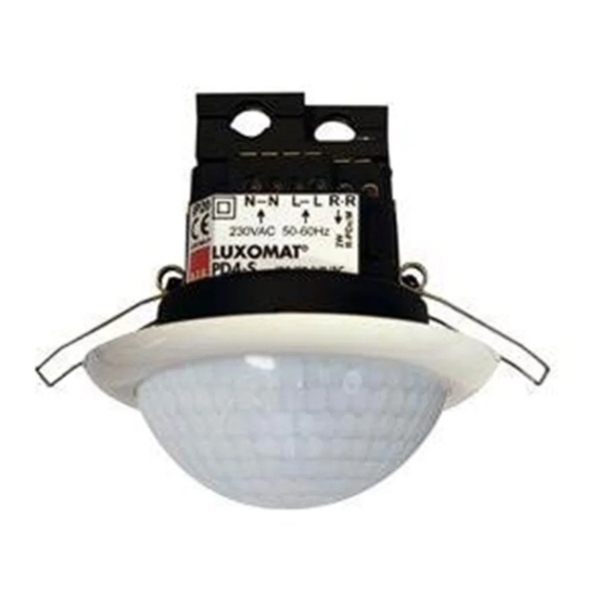
LUXOMAT
Installation and Operating Instruction for B.E.G. - Occupancy detector PD4-M-2C-SM/-FC/ -FM
1. Mounting preparation
Work on the 230 V mains supply
may only be carried out by quali-
fied professionals or by instructed
persons under the direction and
supervision of qualified skilled
electrical personnel in accordance
with electrical regulations.
Disconnect supply before installing!
The device is not suited for safe
disconnection of the mains supply.
When in Master/Slave mode of
operation, the Master-appliance must
always be installed at the location
where there is least daylight.
3a. Hardware configuration SM
Position LED's and potentiometers
Potentiometer 3 Time Channel2
Potentiometer 2 Time Channel1
Potentiometer 1 Lux Channel1
40
LED 1 green
LED 2 red
LED 3 white
4a. Position potentiometers DIP-Switch SM
1
40
OFF
VA
Surface mounting
LED
DIP 1 Fully automatic/semi automatic mode
DIP 2 LED ON/OFF
DIP 3 Change between corridor mode and standard mode
The DIP switch settings are overriden using the remote control.
5. DIP-switch functions
DIP-
ON
switch
1
Semi automatic mode
2
LED OFF
3
Corridor mode
2a. Installation LUXOMAT
®
PD4-M-2C-SM
The detector must be installed
on a solid and level surface.
closed
The circular cover ring
open
must be removed prior to
assembly. To do this, twist the
lens anticlockwise through ap-
proximately 5° and lift off.
Having connected up the
wires in accordance with
regulations, secure the
detector with 2 screws. After
installation replace the lens
and lock (turn clockwise).
Mains to be connected.
3b. Hardware configuration FC
Position LED's and potentiometers
1 2 3
40
LED 1 green
LED 2 white
LED 3 red
4b. Position DIP-Switch FC
2
3
ON
OFF
ON
HA
DIP
COR
DIP 1 Fully automatic/semi automatic mode
DIP 2 LED ON/OFF
DIP 3 Change between corridor mode and standard mode
The DIP switch settings are overriden using the remote control.
OFF
Fully automatic mode
DIP
LED ON
Standard mode
PD4-M-2C/PD4-S
®
2b. Installation LUXOMAT
PD4-M-2C-FC
1
2 3
1
2 3
Potentiometer 1 Lux Channel1
Potentiometer 2 Time Channel1
Potentiometer 3 Time Channel2
1
2
False ceiling mounting
Corridor function: After deactivation by an external push
button, the detector switches off and returns to automatic
mode after 5 sec.
ON
OFF
1
2
3
The DIP settings are enabled again by:
• Adjusting the DIP switches when closed
• Reset with test sun setting at the potentiometers
• Reset when open
®
2c. Installation LUXOMAT
PD4-M-2C-FM
A circular opening of
diameter 68 mm must first
of all be produced in the
ceiling.
Having connected up the
cables in accordance with
regulations, the detector is
inserted into the opening
as shown in the drawing
opposite and fixed into
position with the assistance
of the spring clip.
3c. Hardware configuration FM
Position LED's and potentiometers
1
1
LED 1 green
LED 2 white
LED 3 red
4c. Position DIP-Switch FM
3
DIP
OFF
Flush mounting
ON
DIP 1 Fully automatic/semi automatic mode
DIP 2 LED ON/OFF
DIP 3 Change between corridor mode and standard mode
The DIP switch settings are overriden using the remote control.
GB
®
The detector can be installed
in conventional inlet-sockets
mounted on the ceiling. The as-
sembly plate enclosed must be
stripped off prior to installation
and secured to the ceiling using
4 screws.
Having connected up the
cables in accordance with
regulations, the detector can be
placed in position as shown in
the drawing opposite and, ap-
plying a little pressure, can then
be locked into position with the
assistance of the spring clips.
( For connections please see
pt. 22!)
2 3
2
3
Potentiometer 1 Lux Channel1
Potentiometer 2 Time Channel1
Potentiometer 3 Time Channel2
1
2
3
DIP
OFF
ON
Advertisement

Related Manuals for B.E.G. LUXMAT PD4-S


Summary of Contents for B.E.G. LUXMAT PD4-S
- Page 1 PD4-M-2C/PD4-S LUXOMAT ® Installation and Operating Instruction for B.E.G. - Occupancy detector PD4-M-2C-SM/-FC/ -FM 1. Mounting preparation 2a. Installation LUXOMAT ® 2b. Installation LUXOMAT ® 2c. Installation LUXOMAT ® PD4-M-2C-SM PD4-M-2C-FC PD4-M-2C-FM Work on the 230 V mains supply The detector must be installed A circular opening of The detector can be installed may only be carried out by quali-...
- Page 2 Option: Remote control IR-PD-2C(-S) 6. Putting into operation / Settings 120 60 50 Initialisation (to be used with IR-PD) In the first 60 seconds after connecting the power supply the LUXOMAT ® PD4-M-2C will go through a self test cycle. During this time the device doesn´t respond to movement, but will stay on the status depending on the B.E.G.
- Page 3 16. Range of Coverage 11. Explanation of the remote control button functions 13a. Behaviour of external push button/IR “Light“ 11a. In the initialisation period walking towards The “Corridor“ and “Light ON/OFF“ functions are mutually 2,50 m exclusive. If both are activated, the detector performs the corridor walking across During initialization phase/self test cycle function.
- Page 4 19. Technical data PD4-Master-2C 20. Wiring diagram 22. PD4-M-2C-SM – Connections Wiring diagram Standard operation Master/Slave Sensor and power supply in one case PD4-M-2C-SM Power supply: 230 V~ ±10 % Power consumption: < 1W PD4-M-2C new Ambient temperature: -25°C to +50°C Degree of protection /class: IP20 / II Settings: Potentiometer, DIP-switch...
Need help?
Do you have a question about the LUXMAT PD4-S and is the answer not in the manual?
Questions and answers