Table of Contents
Advertisement
Quick Links
LUXOMAT
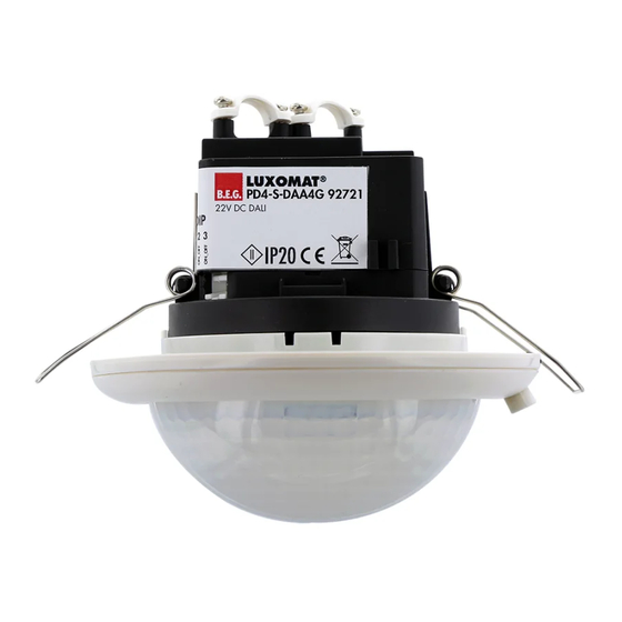
Installation and Operating Instruction for B.E.G. DALI compact solution PD4-M-DAA4G
1. Product information
•
Flexible compact DALI solution designed for conference
rooms, training rooms and classrooms
•
High-sensitivity occupancy detector with the capability to
address up to 64 DALI electronic ballasts automatically, with
segmented control via 4 groups
•
3 lighting zones:
o A for main lighting with segmented constant light regulation
via 3 DALI groups and offset control
o B for lectern or blackboard lighting via separate DALI group
o C for lectern or blackboard lighting via integrated switching
relay
•
High performance switching relay with various operating
modes, e.g. DALI cut-off function, HVAC, blackboard lighting,
etc.
•
Quick commissioning and maintenance processes with
smartphone/tablet app (Android, iOS) – PC tool not required
•
Manual switching and dimming available with conventional
switches
•
Extension of detection area possible with slave devices
•
Plug & Play with broadcast telegrams and basic functions.
Full range of functions can only be activated with the B.E.G.
IR-Adapter and a smartphone or tablet (Android, iOS)
2. Safety advice
Work on electrical equipment should only be undertaken
!
by qualified electricians or by trained personnel under the
instruction and supervision of a trained electrician, according
to the regulations for electrical installation.
Turn off the mains supply before fitting.
!
This device is not to be used to isolate other equipment from
!
the mains supply.
After inserting the connection cable, fit the supplied cover to
!
the detector.
The push button inputs and the D+/D- terminals must not be
!
connected to the mains supply.
3. Operation
3.1 General
The PD4-M-DAA4G is a highly sensitive ceiling-mounted occupancy
detector based on passive infrared motion detection, with integrated
DALI controller, DALI power supply and push button control. If
people, animals or other heat sources move within the detection
area, the detector can dim and switch any DALI-controlled electronic
ballast-driven lights, taking account of ambient light levels, such
that a predefined room lighting level is constantly maintained.
Slave devices, type PD4-S-DAA4G, can be installed to expand the
detection area.
See FIGURE 3.1, Detection diagram
3.2 Groups and lighting zones
See Figure 3.2, Grouping principles
There are three lighting zones (areas for a lighting purpose) availab-
le which can be parameterised by means of a predefined grouping
principle of the integrated DALI control unit and an operating mode
of the integrated relay.
3.2.1. Lightning zone A (main lightning)
The PD4-M-DAA4G allows you to compensate for differences in
brightness due to daylight coming from one side of a room fully
automatically, using segmented constant light regulation in lighting
zone A across 3 groups. Fittings with DALI electronic ballasts are
thus grouped as follows:
Group 1: for areas with little daylight
areas away from the windows
Group 2: for neutral areas
for example the central lighting run
Group 3: for areas which may have strong daylight
areas near the windows
Groups 2 and 3 can be set up with a negative offset between 0%
and 25%, and will then scale back their lighting output in relation
to Group 1. In extreme lighting situations (very bright daylight or no
daylight), both offset settings will be automatically reduced to 0%.
®
PD4-M-DAA4G
3.2.2. Lightning zone B and C (lectern or blackboard lightning)
For teacher or blackboard lighting, lighting zone B (via DALI group
4) and/or lighting zone C (via integrated relay) are available.
In lighting zones B and C, automatic constant light regulation is
disregarded.
3.3. Integrated relay with operating modes
There are 7 different operating modes available on the integrated
bistable relay (potential-free, NO). These cannot be combined:
•
"Cut-off" – standby current consumption of connected DALI
electronic ballasts is automatically minimised
•
"HVAC" – heating, ventilation and air-conditioning units are
automatically controlled for energy efficiency, depending on
motion detection in the room, using a separately-set follow-up
time
•
"Zone C" – activates lighting zone C with push button input
C, for example to provide teacher or blackboard illumination
without a DALI electronic ballast. The automatic mode depends
on the settings for lighting zone B (Group 4).
•
"CdS" – "cadmium sulfide" – relay works as
photo electric switch
"None" for "no function" – relay is not actuated
•
•
"Alarm impulse" (via operating mode HVAC) – The relay only
closes for 2.5 seconds if at least 3 movements have been
detected during a time period of 9 seconds. This function can
be used to display a presence in the room on external visuali-
sations. (Warning: The device does not fulfil the requirements of
DIN EN50131-2-2 and therefore cannot be used in professional
intrusion detection systems.
"Impulse function" (via operating mode HVAC) – The impulse
•
function can be used to control external HVAC systems.
All 9 s will be set an impulse lasting 2.5 s
See FIGURE 3.3, function diagram
3.4. Full automatic / semi-automatic mode
Lighting zones A and B can be set individually to full automatic or
semi-automatic mode. Lighting zone C always works with the set-
tings from lighting zone B. In full automatic mode, the light is turned
on automatically when motion is detected and ambient light is low
enough, and turned off after an adjustable follow-up time and/or
when ambient light is bright enough. Semi-automatic mode works in
a similar fashion, except that switching on the lights must take place
via a push button (
manual ON/ auto OFF).
3.5. Push button functions
Conventional NO push buttons can be used.
A short press on all three push buttons, A, B and C, turns the light
in each lighting zone on or off. A long press (> 2 seconds) on push
buttons A and B leads to manual dimming (brightness up or down –
another long press reverses the dimming direction).
Special feature in full automatic mode: if you want to use a short
press to deliberately switch off the light in the room, for example
to show a film or set up a projector, the light remains off until the
follow-up time has expired.
3.6. IR-Adapter
Lighting zones can only be parameterised sending infrared signals
via Smartphone app. Factory setting of the detector is broadcast
mode (white LED shines permanently). So it is possible to check all
DALI bus connections and pushbutton connections without parame-
terising. To send infrared signals via the Smartphone or a tablet,
an IR-Adapter (part no. 92726) is required, which must be charged
periodically, and has to be plugged in to the audio socket of the
Smartphone or tablet.
See FIGURE 3.6 IR-Adapter
4. Wiring
See FIGURE 4, Wiring diagram
4.1. DALI
For wiring the DALI bus, standard electrical installation cabling
can be used (e.g. NYM-J 5x1,5). The recommended wire gauge is
2x0,5 mm² (up to 100m), 2x1,0 mm² (up to 200 m), 2x 1,5 mm²
(up to 300 m). A total length of 300 metres must not be exceeded.
The DALI bus is factory-fitted with reverse polarity protection.
4.2. Push buttons
For push button connections, also standard electrical installation
cabling can be used (e.g. NYM-J 5x1.5 or J-Y(ST)Y-8x2x0.28), with
a minimum wire gauge of 0.28 mm² and a maximum length of 50
metres. For use in industrial environments, it is recommended to
separate all pushbutton wires from other loads and to guide them
in a wired cable.
4.3. Connecting terminal
The connectors are suitable for solid wires with a cross-section of up
to 2.5 mm². Ferrules must be used with stranded wires.
4.3.1. Connecting for false ceiling
The ceiling-mount version of the PD4-M-DAA4G is fitted with 2
removable multipole screw terminals. When installing the wires,
these two terminals can each be pulled out. After connecting the
wires, it is important that the terminals are fixed back onto the sup-
port and into each recess. Caution: only use the terminals supplied.
These are designed so that it is not possible to reverse polarity or
to swap them.
4.3.2. Connecting for surface
The surface mount version of the PD4-M-DAA4G is fitted with 2
multipole screw terminals on its socket. Fastening of the detector to
the socket is designed such that the contact pins are automatically
connected and it is not possible to reverse polarity or to swap them.
5. Mounting
5.1. General
The ideal mounting location is inside, 2.5 to 3 metres high, on the
ceiling. Ventilation units and other heat sources (e.g. copiers) should
not be in the immediate vicinity of the detector, as otherwise "false
alarm" motion detection events may be triggered.
5.2. Light sensor
The exact mounting location of the detector depends on two
things. One is the area in which motion is to be detected. The
other factor that influences detector position in the room is that light
measurement has to take place in the lighting area of DALI Group 1
(potentially dark areas). The exact mounting location of the detector
does not have to be precisely above the lighting area of DALI
Group 1, because of the vertically-adjustable (by max. 30°) light
sensor on the cover ring, and because the detector can be turned
in all directions horizontally. Normally, it is recommended that the
detector is mounted centrally in the room, near or adjacent to the
DALI Group 1 lighting area.
5.3. Ceiling installation variant
First, a round opening 100 mm in diameter must be made in the
ceiling. After properly connecting the cables, the detector is inserted
into the opening and if necessary turned on its axis until the light
sensor can be pointed to the probable darkest area of the room.
The detector is then fixed with screws through the mounting bracket.
See FIGURE 5.3, Ceiling mounting
5.4. Mounting SM
The detector must be fixed on a smooth, solid surface. First, 2
holes must be drilled in the ceiling, at a distance of 67 mm from
each other, such that an imaginary straight line between the two
drilled holes points to the probable darkest area of the room (e.g.
the wall opposite the window side). Later adjustment of the light
sensor's horizontal direction is still possible after fastening (can be
turned by about 80°). Before mounting, the lens must be removed.
Turn the lens about 5° anticlockwise and remove it. After properly
connecting the wiring, the detector must be fixed with 2 screws.
Then reattach the lens, turning it clockwise.
See FIGURE 5.4 Surface mounting
6. Self-test cycle
In the first 60 seconds from when the mains voltage is turned on, the
detector runs through a self-test cycle. During this period, the device
does not react to movement.
7. Commissioning without IR-Adapter
The PD4-M-DAA4G can also be put into service with basic functi-
onality without changing any settings. Out of the box, the detector
works in Broadcast mode (white LED shines permanently), which
can only be changed over to Group mode with the remote control
(smartphone or tablet + IR-Adapter + app) and the command "UN-
LOCK". All push buttons are activated in Broadcast mode (switching
and dimming).
See FIGURE 7, Potentiometers and DIP switches
EN
Advertisement
Table of Contents

Related Manuals for B.E.G. LUXOMAT PD4-M-DAA4G


Summary of Contents for B.E.G. LUXOMAT PD4-M-DAA4G
- Page 1 LUXOMAT ® PD4-M-DAA4G Installation and Operating Instruction for B.E.G. DALI compact solution PD4-M-DAA4G 3.2.2. Lightning zone B and C (lectern or blackboard lightning) 4.2. Push buttons 1. Product information For teacher or blackboard lighting, lighting zone B (via DALI group For push button connections, also standard electrical installation •...
- Page 2 PD4-M-DAA4G 92591 0 - 240VAC, 50/60Hz 00 W, 10A, cosφ=1 The following settings can be made via potentiometer and DIP 10. LED Indication Only applies to all connected, factory-new 50 VA, cosφ=0.5, switches: XOMAT ® DALI ECG (Factory-new = With short Indication white green...
- Page 3 12.2 Step 2: New addressing process BRIGHTER Soft Start Important note for slave operation: - Dim up to LUX set value for lighting zone A - Closed: Fast dimming up to MAX and broadcast Important note for slave operation: connect slave devices only after - Open: Slow dimming up to MAX setting up addressing, or else ensure that, while auto-addressing takes place (all LEDs blinking quickly), no-one remains in any slave...
- Page 4 16. Technical data "Open lock" button / DALI configuration 100% Power supply: 110-240 V AC , 50 / 60 Hz mode is activated Area of coverage: circular, 360° Range of coverage: Ø 24m transverse Push button "ADD" Ø 8m towards / Alternative addressing Ø...
- Page 5 LUXOMAT ® PD4-M-DAA4G Figures PD4-M-DAA4G-SM/FC 3.1. 3.6. 5.2. PD4-DAA4G_abb ba.pdf 29.05.2017 12:49:02 5.3. 100 mm walking across walking towards seated 3.2. Master N NO NO PBA PBB PBC DA+ DA– PBA PBB PBC 5.4. open close DALI BUS DA– DA+ DA– DA+ DA–...
Need help?
Do you have a question about the LUXOMAT PD4-M-DAA4G and is the answer not in the manual?
Questions and answers