
Related Manuals for Banner Q3XTBLD200-Q8


Summarization of Contents
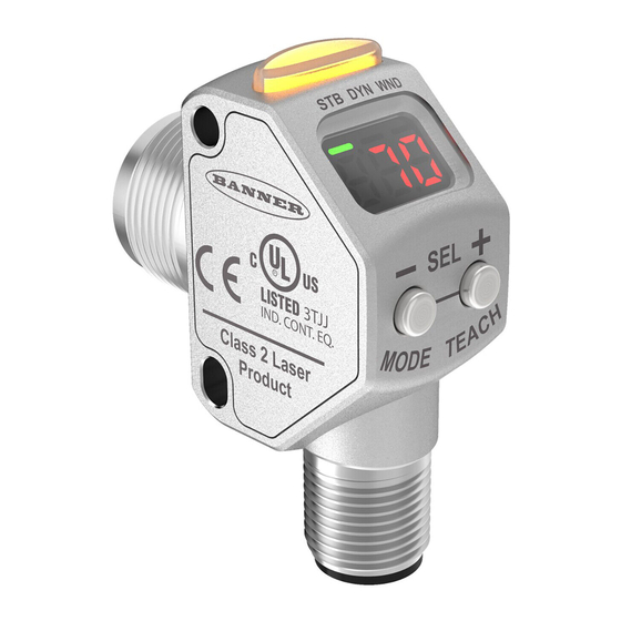
Product Description and Features
Product Models
Lists available Q3X sensor models with their sensing ranges and output types.
Product Overview
Provides a general description of the Q3X sensor's capabilities and application benefits.
Sensor Features
Highlights key physical and functional features of the Q3X laser contrast sensor.
Laser Safety Information
Details laser specifications and critical safety precautions for laser operation and eye protection.
Display and Indicator Functions
Explains the function of the 3-digit display and various indicator lights on the sensor.
Sensor Control Buttons
Describes the function of the sensor's control buttons for setup and operation.
Installation and Setup
Safety Label Installation
Instructions for applying the required safety label to the sensor cable.
Sensor Orientation Guide
Guidance on properly orienting the sensor for optimal detection performance.
Sensor-to-Background Positioning
Table specifying sensing ranges and recommended background suppression distances.
Sensor Mounting Procedure
Steps for physically mounting the sensor onto equipment or a bracket.
Wiring Diagram and Pinout
Illustrates the sensor's electrical connections and pinout details.
Cleaning and Maintenance
Procedures for keeping the sensor window clean for peak performance.
Sensor Programming and Configuration
Setup Mode Navigation
Describes how to access and navigate the sensor's setup menu for configuration.
Output Operation Modes
Configuration option to select light or dark operate mode for the output signal.
TEACH Mode Selection
Allows selection of different TEACH modes for sensor calibration and setup.
Offset Percentage Adjustment
Sets the offset percentage for Window, Light, or Dark Set TEACH modes.
Response Speed Settings
Configures the sensor's response time for different application speeds.
Output Timing Delays Configuration
Sets delays for output signals, including ON delay, OFF delay, and one-shot pulse.
Input Wire Functionality
Configures the function of the sensor's input wire, such as remote TEACH or sync.
Sensitivity Adjustment
Adjusts the sensor's sensitivity for optimal performance in varying conditions.
Cut-Off Operation Modes
Defines sensor behavior with background suppression when targets are beyond a set distance.
Display View Options
Selects display orientation (right-reading/inverted) and sleep mode behavior.
Exiting Setup Mode
Describes how to exit the setup menu and return to Run mode.
Factory Default Reset
Restores the sensor to its original factory default settings.
Manual Gain Adjustment
Allows direct manual adjustment of the sensor's gain.
Remote Input Programming
Explains how to program and control the sensor remotely using its input wire.
Remote TEACH Mode Selection
Details how to select TEACH modes via pulsed signals on the remote input.
Remote Factory Default Reset
Instructions for resetting the sensor to factory defaults via remote input pulses.
Button Lock and Unlock
Features for locking/unlocking buttons to prevent unauthorized programming changes.
TEACH Procedures and Sync Operation
Detection Reliability Assessment
Method to assess detection reliability by comparing light and dark target signal values.
Two-Point Static TEACH
Step-by-step guide for performing a two-point static teach on the sensor.
Dynamic TEACH Procedure
Procedure for dynamic teaching, suitable for applications where the machine cannot be stopped.
Window Set TEACH
Procedure for setting a sensing window using offset percentage for precise detection.
Light Set TEACH
Procedure for setting a switching threshold with an offset below the presented condition.
Dark Set TEACH
Procedure for setting a switching threshold with an offset above the presented condition.
Sync Master/Slave Configuration
Configuration for using two sensors together to eliminate crosstalk.
Specifications and Performance
Laser Beam Specifications
Details the visible red Class 2 laser used by the sensor.
Power Requirements
Specifies the required supply voltage and power consumption parameters.
Performance Characteristics
Includes repeatability, delay at power up, and maximum torque for mounting.
Connectivity
Describes the sensor's M12 Euro-style connector and input wire specifications.
Output Specifications
Details the bipolar output configuration and rating, including ambient light immunity.
Configurable Response Speed
User-selectable response speeds for optimizing detection performance.
Physical Construction
Information on the materials and build of the sensor's housing and components.
Beam Spot Pattern
Graphical data illustrating the laser beam spot dimensions at various distances.
Overcurrent Protection
Guidance on necessary overcurrent protection for electrical connections.
Performance Curves
Graphs showing excess gain versus distance for different sensor models.
Physical Dimensions
Technical drawings detailing the sensor's physical dimensions.
Troubleshooting
Troubleshooting Codes and Resolutions
Lists common error codes and their corresponding resolutions for diagnosing issues.
Accessories
Cordsets
Details available cordsets for connecting the sensor, including types and pinouts.
Mounting Brackets
Information on mounting brackets compatible with the sensor.
Need help?
Do you have a question about the Q3XTBLD200-Q8 and is the answer not in the manual?
Questions and answers