
Related Manuals for Banner Q3X


Summary of Contents for Banner Q3X
- Page 1 Q3X Laser Contrast Sensor Instruction Manual Original Instructions 181485 Rev. B 4 March 2015 181485...
-
Page 2: Table Of Contents
4.1 Performance Curves ....................... 24 4.2 Dimensions ........................... 26 5 Abbreviations ......................27 6 Troubleshooting ......................29 7 Accessories ........................30 7.1 Cordsets ..........................30 7.2 Brackets ..........................30 8 Contact Us ........................32 9 Banner Engineering Corp Limited Warranty ..............33... -
Page 3: Product Description
™ The Q3X Sensor is an Expert laser diffuse contrast sensor for low contrast detection application. Some models of the Q3X are able to ignore targets beyond a factory-set background suppression distance. This innovative combination of low contrast diffuse sensing of targets while ignoring objects beyond the region of interest eliminates the biggest problem of diffuse mode sensing, namely changing background conditions affecting the contrast detection. -
Page 4: Features
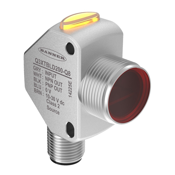
Q3X Laser Contrast Sensor 1.3 Features 1. Output Indicator (Amber) 2. Display 3. Buttons Figure 1. Sensor Features 1.3.1 Display and Indicators 1. Stability Indicator (STB = Green) 2. Active TEACH Indicators • DYN = Dynamic TEACH selected (Amber) •... -
Page 5: Buttons
Q3X Laser Contrast Sensor • WND on—Symmetric Window thresholds are active. The switch points are above and below 100 by the offset percentage 1.3.2 Buttons Use the sensor buttons (-)(MODE) and (+)(TEACH) to program the sensor. Sensor Programming on page 9 for programming instructions. - Page 6 Q3X Laser Contrast Sensor Class 2 Laser Safety Notes Low-power lasers are, by definition, incapable of causing eye injury within the duration of a blink (aversion response) of 0.25 seconds. They also must emit only visible wavelengths (400 to 700 nm). Therefore, an ocular hazard may exist only if individuals overcome their natural aversion to bright light and stare directly into the laser beam.
-
Page 7: Installation
Q3X Laser Contrast Sensor 2 Installation 2.1 Install the Safety Label The safety label must be installed on Q3X sensors that are used in the United States. NOTE: Position the label on the cable in a location that has minimal chemical exposure. -
Page 8: Wiring Diagram
Q3X Laser Contrast Sensor 2.4 Wiring Diagram 10-30V dc – Load Load 1 = Brown Input 2 = White Wire 3 = Blue 4 = Black 5 = Gray NOTE: Open lead wires must be connected to a terminal block. -
Page 9: Sensor Programming
Q3X Laser Contrast Sensor 3 Sensor Programming Program the sensor using the buttons on the sensor or the input wire (limited programming options; see Remote Input page 13 for details). In addition to programming the sensor, use the input wire to disable the buttons for security, preventing unauthorized or accidental programming changes. -
Page 10: Response Speed
Q3X Laser Contrast Sensor • —minimum • —10% • —20% • —30% • —40% • —50% Dark Set options: • —minimum • —25% • —50% • —100% • —200% 3.1.4 Response Speed Use this menu to select the response speed. The default is 1 millisecond. -
Page 11: Input Wire Function
Q3X Laser Contrast Sensor Output OFF Delay ON Delay 1-Shot Time (D = 1 - 9999 ms) Figure 5. Output Timing Delays When either is chosen, the sensor returns to the Setup menu and additional options become available to set the timer(s): •... -
Page 12: Sensitivity
Q3X Laser Contrast Sensor • —Slave sync line output for two-sensor cross-talk avoidance To configure sensors for master-slave operation, see Sync Master/Slave on page 22. 3.1.7 Sensitivity Use this menu to set the sensitivity. The default is standard. • —High sensitivity. Use this setting for low contrast sensing •... -
Page 13: Reset To Factory Defaults
Q3X Laser Contrast Sensor 3.1.11 Reset to Factory Defaults Use this menu to restore the sensor to the factory default settings. Select to return to the sensor menu without restoring the defaults. Select to restore the sensor to the factory default settings and return to Run mode. -
Page 14: Select The Teach Mode Using The Remote Input
Q3X Laser Contrast Sensor = Set Remote Pulse Timing (T) Input (gray wire is input wire) 0.04 seconds < T < 0.8 seconds Timing between Pulse groups > 1 second Starts selected Teach (same function as pressing Teach Button for > 2 sec) -
Page 15: Reset To Factory Defaults Using The Remote Input
Q3X Laser Contrast Sensor 3.3.2 Reset to Factory Defaults Using the Remote Input Eight-pulse the remote input to apply the factory defaults and return to Run mode. NOTE: The input wire function remains at remote teach input ( 3.4 Locking and Unlocking the Sensor Buttons Use the lock and unlock feature to prevent unauthorized or accidental programming changes. - Page 16 Q3X Laser Contrast Sensor 2nd Taught 1st Taught Condition Condition Sensor positions threshold midway between taught conditions Output OFF Output ON Darkest Position Most Light (no signal) adjusted by (saturated Manual Adjust signal) Figure 7. Two-Point TEACH (Light Operate shown) NOTE: The sensor must be set to to use the following instructions.
-
Page 17: Dynamic Teach
Q3X Laser Contrast Sensor Table 3: Expected TEACH Behavior for Two-Point Static TEACH Condition TEACH Result Display At least one taught condition is Sets the threshold between the two The current NSS displays. between the minimum and maximum taught conditions. -
Page 18: Window Set
Q3X Laser Contrast Sensor Method Action Result Push Button Press TEACH to teach the target. The sensor begins sampling target intensity information and Remote Input Single-pulse the remote input. flash alternately on the display. The DYN indicator flashes. 4. Present the targets. -
Page 19: Light Set
Q3X Laser Contrast Sensor NOTE: To program the sensor using remote input, remote input must be enabled ( 1. Present the target. Method Action Result Push Button Present the target. The sensor-to-target distance must be within the The target's value displays. - Page 20 Q3X Laser Contrast Sensor Threshold position adjusted by Manual Adjust Sensor positions the threshold slightly below the presented condition Output OFF Output ON Darkest Condition Most Light (no signal) Presented (saturated signal) Figure 10. Light Set (Light Operate shown) NOTE: The sensor must be set to to use the following instructions.
-
Page 21: Dark Set
Q3X Laser Contrast Sensor Condition TEACH Result Display The taught condition is brighter than Sets the threshold at the maximum The current NSS displays. the maximum signal value limit. level minus the value. 3.5.6 Dark Set Dark set sets a switching threshold a user-selectable percent offset above the presented condition. Use the menu to set the offset percentage. -
Page 22: Sync Master/Slave
3.6 Sync Master/Slave Two Q3X sensors may be used together in a single sensing application. To eliminate crosstalk between the two sensors, configure one sensor to be the master and one to be the slave. In this mode, the sensors alternate taking measurements and the response speed is 25 ms. -
Page 23: Sensor Menu Map
Q3X Laser Contrast Sensor 3.7 Sensor Menu Map Top Menu Sub Menu BOTH sets selection BOTH Output Operation Light Operate default setting) Dark Operate BOTH Teach Process Selection Two-Point Static Teach Dynamic Teach Window Set Light Set Dark Set Offset Percentage BOTH (min, 10, 20, 30, 40, 50) - Window &... -
Page 24: Specifications
Q3X Laser Contrast Sensor 4 Specifications Sensing Beam Response Speed Visible red Class 2 laser, 655 nm User selectable: Supply Voltage (Vcc) • —250 microseconds 10 to 30 V dc • —1 millisecond Power and Current, exclusive of load Supply Power: < 675 mW •... - Page 25 Q3X Laser Contrast Sensor Q3XTBLD Models 1000 - 0.5 - 1.0 - 1.5 - 2.0 - 2.5 1000 DISTANCE (mm) DISTANCE (mm) Figure 13. Excess Gain for Standard Sensitivity Figure 14. Beam Pattern NOTE: For High Sensitivity the Excess Gain increases by a factor of 1.5. For Low Sensitivity the Excess Gain decreases by a factor of 0.75...
-
Page 26: Dimensions
Q3X Laser Contrast Sensor 4.2 Dimensions All measurements are listed in millimeters (inches), unless noted otherwise. 35.26 1.21 24.30 Ø3.30 1.50 RECEIVER 12.05 M18 X 1-6g 24.10 34.80 47.10 18.05 3.50 EMITTER 1.30 3.80 18.00 14.90 3.30 M12 X 1-6g... -
Page 27: Abbreviations
Q3X Laser Contrast Sensor 5 Abbreviations The following table describes the abbreviations used on the sensor display. Abbreviation Description No light received (loss of signal) The signal is saturated One shot First One point Second Two-point static TEACH Bottom—The sensor is at minimum gain during a manual adjustment or after a TEACH Calibration set Cutoff—A target is detected in the background (models with background suppression only) - Page 28 Q3X Laser Contrast Sensor Abbreviation Description Output operation Offset percentage Reset to factory defaults Sensitivity Input wire = remote teach function Set (used in the TEACH procedures) Standard sensitivity Slave Response speed Stop Teach process selection Top—The sensor is at maximum gain during a manual adjust or after a TEACH...
-
Page 29: Troubleshooting
Q3X Laser Contrast Sensor 6 Troubleshooting Table 8: Troubleshooting Codes Code Description Resolution No light received For some applications, reposition the sensor or the target The signal is saturated For some applications, reposition the sensor or the target Table 9: Error Codes... -
Page 30: Accessories
Q3X Laser Contrast Sensor 7 Accessories 7.1 Cordsets All measurements are listed in millimeters, unless noted otherwise. 5-Pin Threaded M12/Euro-Style Cordsets (Single Ended) Model Length Style Dimensions Pinout (Female) MQDC1-501.5 0.50 m (1.5 ft) 44 Typ. MQDC1-506 1.83 m (6 ft) - Page 31 Q3X Laser Contrast Sensor SMBQ4X.. SMB18FA.. • Swivel bracket with tilt • Swivel bracket with tilt and and pan movement for pan movement for precision precision adjustment adjustment • Easy sensor mounting to • Easy sensor mounting to extruded rail T-slots extruded rail T-slots •...
-
Page 32: Contact Us
Email: salesindia@bannerengineering.com Pune 411016, India Mexico Address: Phone: +52 81 8363 2714 or 01 800 BANNERE (toll free) Banner Engineering de Mexico Monterrey Head Office Website: www.bannerengineering.com.mx Edificio VAO Av. David Alfaro Siqueiros No.103 Col. Valle Oriente C.P.66269 Email: mexico@bannerengineering.com... -
Page 33: Banner Engineering Corp Limited Warranty
9 Banner Engineering Corp Limited Warranty Banner Engineering Corp. warrants its products to be free from defects in material and workmanship for one year following the date of shipment. Banner Engineering Corp. will repair or replace, free of charge, any product of its manufacture which, at the time it is returned to the factory, is found to have been defective during the warranty period.