Banner Q4X Quick Start Manual
Stainless steel laser sensor with dual discrete outputs and io-link
Hide thumbs
Also See for Q4X:
- Instruction manual (46 pages) ,
- Quick start manual (13 pages) ,
- User manual (2 pages)
Table of Contents
Advertisement
Quick Links
Q4X Stainless Steel Laser Sensor with Dual
Discrete Outputs and IO-Link
Quick Start Guide
Class 1 laser CMOS sensor with dual outputs and IO-Link. Patent pending.
This guide is designed to help you set up and install the Q4X Sensor with Dual Discrete Outputs and IO-Link. For complete information on
programming, performance, troubleshooting, dimensions, and accessories, please refer to the Instruction Manual at www.bannerengineering.com.
Search for p/n 190074 to view the Instruction Manual. Use of this document assumes familiarity with pertinent industry standards and practices.
For illustration purposes, the threaded barrel model Q4X images are used throughout this document.
WARNING:
• Do not use this device for personnel protection
• Using this device for personnel protection could result in serious injury or death.
• This device does not include the self-checking redundant circuitry necessary to allow its use in personnel safety
applications. A device failure or malfunction can cause either an energized (on) or de-energized (off) output condition.
Features
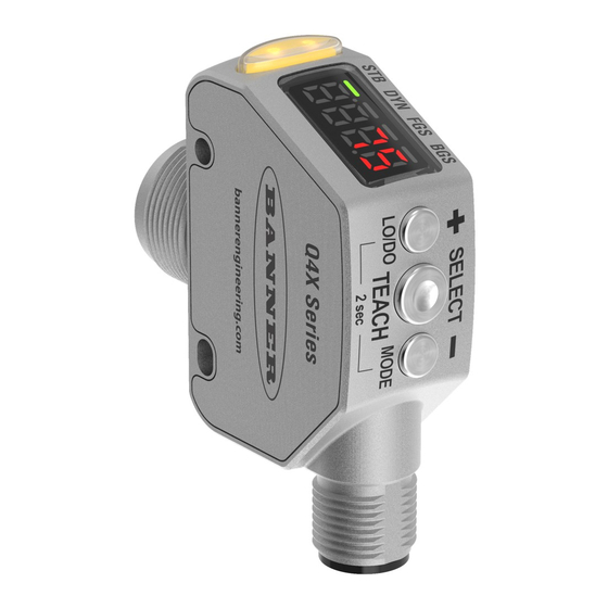
Figure 1. Sensor Features—Threaded Barrel Models
1
Display and Indicators
The display is a 4-digit, 7-segment LED. The main screen is the Run mode screen.
For 2-pt, BGS, FGS, and DYN TEACH modes, the display shows the current distance to the target in millimeters. For dual TEACH mode, the display
shows the percentage matched to the taught reference surface. A display value of
Figure 3. Display in Run Mode
1
Note: The indicators represent the currently selected channel. However, if Output 2 is set to something other than LO, DO, or
Complementary, then the indicators represent the Channel 1 status.
Output Indicator
• On—Output is on
• Off—Output is off
Stability Indicator (STB)
• On—Stable signal within the specified sensing range
• Flashing—Marginal signal, the target is outside the limits of the
specified sensing range, or a multiple peak condition exists
• Off—No target detected within the specified sensing range
Buttons
Use the sensor buttons (SELECT)(TEACH), (+)(CH1/CH2), and (-)(MODE) to program the sensor.
Original Document
190073 Rev. G
2
1. Output Indicator (Amber)
2. Display
3. Buttons
3
2
1. Stability Indicator (STB—Green)
2. Active TEACH Indicators
indicates the sensor has not been taught.
• DYN—Dynamic (Amber)
• FGS—Foreground Suppression (Amber)
• BGS—Background Suppression (Amber)
Active TEACH Indicators (DYN, FGS, and BGS)
• DYN, FGS, and BGS all off—Two-point TEACH mode selected
(default)
• DYN on—Dynamic TEACH mode selected
• FGS on—Foreground suppression TEACH mode selected
• BGS on—Background suppression TEACH mode selected
• DYN, FGS, and BGS all on—Dual TEACH mode selected
18 April 2022
Figure 2. Sensor Features—Flush Mount Models
1
2
3
190073
Advertisement
Table of Contents

Related Manuals for Banner Q4X


Summary of Contents for Banner Q4X
- Page 1 Class 1 laser CMOS sensor with dual outputs and IO-Link. Patent pending. This guide is designed to help you set up and install the Q4X Sensor with Dual Discrete Outputs and IO-Link. For complete information on programming, performance, troubleshooting, dimensions, and accessories, please refer to the Instruction Manual at www.bannerengineering.com.
-
Page 2: Laser Description And Safety Information
Pulse Duration: 7 µs to 2 ms Installation Install the Safety Label The safety label must be installed on Q4X sensors that are used in the United States. Figure 4. Safety Label Installation Note: Position the label on the cable in a location that has minimal chemical exposure. -
Page 3: Sensor Programming
See the following figures for examples of correct and incorrect sensor-to-target orientation as certain placements may pose problems for sensing Performance Curves for some targets. The Q4X can be used in the less preferred orientation and provide reliable detection performance; refer to the the minimum object separation distance required for each case. -
Page 4: Setup Mode
Q4X Stainless Steel Laser Sensor with Dual Discrete Outputs and IO-Link Setup Mode Access Setup mode and the sensor menu from Run mode by pressing and holding MODE for longer than 2 seconds. Use to navigate through the menu. Press SELECT to select a menu option and access the submenus. Use to navigate through the submenus. - Page 5 Q4X Stainless Steel Laser Sensor with Dual Discrete Outputs and IO-Link Figure 13. Sensor Menu Map—Channel 1 Channel 1 Top Menu Sub Menu Output CH1 Light Operate default setting) Dark Operate Teach Selection CH1 Two-Point Static Teach Dynamic Teach Foreground Suppression...
-
Page 6: Basic Teach Instructions
Basic TEACH Instructions Use the following instructions to teach the Q4X sensor. The instructions provided on the sensor display vary depending on the type of TEACH mode selected. Two-point TEACH is the default TEACH mode. 1. Press and hold TEACH for longer than 2 seconds to start the selected TEACH mode. -
Page 7: Manual Adjustments
Q4X Stainless Steel Laser Sensor with Dual Discrete Outputs and IO-Link • Dual intensity + distance —Dual mode records the distance and amount of light received from the reference surface. See Dual Mode Reference Surface Considerations on page 11 for more information about selecting a reference surface. The output switches when an object passing between the sensor and the reference surface changes the perceived distance or amount of returned light. -
Page 8: Specifications
Q4X Stainless Steel Laser Sensor with Dual Discrete Outputs and IO-Link Specifications Sensing Beam Response Speed Visible red Class 1 laser, 655 nm User selectable, 100, 110, 300, and 310 mm models: Supply Voltage (Vcc) • —1.5 milliseconds 10 V DC to 30 V DC (Class 2 supply) (10% max ripple within limits) Power and Current Consumption, exclusive of load •... -
Page 9: Industry Canada
Q4X Stainless Steel Laser Sensor with Dual Discrete Outputs and IO-Link Excess Gain using a 90% White Card—100/110/300/310 mm Models Table 6: Excess Gain ( Excess Gain Response Speed (ms) · at 25 mm (100/300 mm models) · at 100 mm (100/300 mm models) ·... -
Page 10: Performance Curves-Threaded Barrel Models
Q4X Stainless Steel Laser Sensor with Dual Discrete Outputs and IO-Link Performance Curves—Threaded Barrel Models Figure 15. Minimum Object Separation Distance (90% to 6% reflectance) Minimum Separation Distance Between Target and Background for: Uniform and Non-Uniform Targets 100 mm Models... -
Page 11: Performance Curves-Flush Mount Models
Optimize reliable detection by applying these principals when selecting your reference surface, positioning your sensor relative to the reference surface, and presenting your target. The robust detection capabilities of the Q4X allows successful detection even under non-ideal conditions in many cases. Typical reference surfaces are metal machine frames, conveyor side rails, or mounted plastic targets. Contact Banner Engineering if you require assistance setting up a stable reference surface in your application. - Page 12 Banner Engineering Corp. Limited Warranty Banner Engineering Corp. warrants its products to be free from defects in material and workmanship for one year following the date of shipment. Banner Engineering Corp. will repair or replace, free of charge, any product of its manufacture which, at the time it is returned to the factory, is found to have been defective during the warranty period. This warranty does not cover damage or liability for misuse, abuse, or the improper application or installation of the Banner product.
- Page 13 Mouser Electronics Authorized Distributor Click to View Pricing, Inventory, Delivery & Lifecycle Information: Banner Engineering Q4XFKLAF610-Q8 Q4XTKLAF300-Q8 Q4XTKLAF600-Q8...
Need help?
Do you have a question about the Q4X and is the answer not in the manual?
Questions and answers