Advertisement
Quick Links
Microlectra bv.
WL200 Series Inverter
Basic Manual
Manual Number: NT3531X
www.microlectra.nl
Single-phase Input 200V class
Three-phase Input
Sep. 2015
Hitachi Industrial Equipment Systems Co., Ltd.
info@microlectra.nl
400V class
Refer to the user manual for detail
Advertisement

Related Manuals for Hitachi WL200 Series


Summary of Contents for Hitachi WL200 Series
- Page 1 Microlectra bv. www.microlectra.nl info@microlectra.nl WL200 Series Inverter Basic Manual Single-phase Input 200V class Three-phase Input 400V class Manual Number: NT3531X Refer to the user manual for detail Sep. 2015 Hitachi Industrial Equipment Systems Co., Ltd.
- Page 2 Microlectra bv. Augustapolder 12. 2992 SR Barendrecht. The Netherlands. www.microlectra.nl info@microlectra.nl...
- Page 3 Introduction Thank you for purchasing the Hitachi WL200 series inverter. Please read this Basic Manual and Instruction manual, and understand perfectly how to handle properly and the safety cautions of the product before operation, for safety and proper usage. Note that this Basic Manual is intended for each product and should be delivered to the end user of the inverter.
- Page 4 2. Wiring WARNING Be sure to ground the inverter. Otherwise, you run the risk of electric shock or fire. - Commit wiring work to a qualified electrician. Otherwise, you run the risk of electric shock or fire. - Before wiring, make sure that the power supply is off. Otherwise, you run the risk of electric shock or fire.
- Page 5 CAUTION - Do not touch the heat sink, which heats up during the inverter operation. Otherwise, you run the risk of burn injury. - The inverter allows you to easily control the speed of motor or machine operations. Before operating the inverter, confirm the capacity and ratings of the motor or machine controlled by the inverter.
- Page 6 UL Cautions, Warnings and Instructions Warnings and Cautions for Troubleshooting and Maintenance (Standard to comply with : UL508C,CSA C22.2 No.14-05) Warning Markings GENERAL: These devices are open type Power Conversion Equipment. They are intended to be used in an enclosure. Insulated gate bipolar transistor (IGBT) incorporating microprocessor technology.
- Page 7 Terminal symbols and Screw size “Use 60/75 C Cu wire only” or equivalent. For models WL200-022S, -004H, -007H, -015H, -022H, -030H, and -040H. “Use 75 C Cu wire only” or equivalent. For models WL200-002S, -004S, -007S, -015S, -055H, -075H -110H, -150H and -185H. Required Inverter Model Screw Size...
- Page 8 Fuse Sizes Distribution fuse size marking is included in the manual to indicate that the unit shall be connected with a Listed Cartridge Nonrenewable fuse, rated 600 Vac with the current ratings as shown in the table below or Type E Combination Motor Controller marking is included in the manual to indicate that the unit shall be connected with, LS Industrial System Co.,Ltd,Type E Combination Motor Controller MMS Series with the ratings as shown in the table below:...
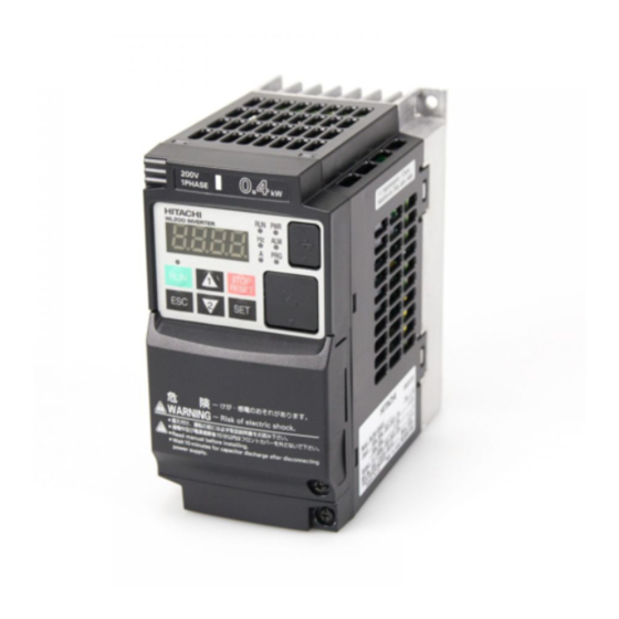
- Page 9 Inverter Specification Label The Hitachi WL200 inverters have product labels located on the right side of the housing, as pictured below. Be sure to verify that the specifications on the labels match your power source, and application safety requirements. Model name...
- Page 10 WL200 Inverter Specifications Model-specific tables for 200V and 400V class inverters The following tables are specific to WL200 inverters for the 200V and 400V class model groups. Item Single-phase 200V class Specifications WL200 inverters, 200V models 002SFE 004SFE 007SFE 015SFE 022SFE Applicable motor 0.75...
- Page 11 WL200 Inverter Specifications, continued… General Specifications Item Specifications Protection structure Note 4) Open type (IP20) Control method Line-to-line sinusoidal PWM method Output frequency range Note 5) 0.10 to 400Hz For maximum frequency, digital command ±0.01%, analog command Frequency accuracy Note 6) ±0.2%(25±10℃)...
- Page 12 Note 4) Protection method is compliant with JEM1030. Note 5) When you operate motor exceeding over 50/60Hz, please inquire about an allowable maximum number of rotations of motor, etc. to motor manufacturer. Note 6) In order to control motors stably, output frequency may exceed over the maximum frequency set by A004 (A204) by max.
- Page 13 Basic System Description A motor control system will obviously include a motor and inverter, as well as a circuit breaker or fuses for safety. If you are connecting a motor to the inverter on a test bench just to get started, that’s all you may need for now. But a system can also have a variety of additional components.
- Page 14 Determining Wire and Fuse Sizes The maximum motor current in your application determines the recommended wire size. The following table gives the wire size in AWG. The “Power Lines” column applies to the inverter input power, output wires to the motor, the earth ground connection, and any other components shown in the “Basic System Description”...
- Page 15 Wire the Inverter Input to a Supply In this step, you will connect wiring to the input of the inverter. First, you must determine whether the inverter model you have required three-phase power only, or single-phase power only. All models have the same power connection terminals [R/L1], [S/L2], and [T/L3].
- Page 16 Three-phase 400V 5.5kW PD/+1 R/L1 S/L2 T/L3 U/T1 V/T2 W/T3 Chassis Ground (M4) Power input Output to Motor Three-phase 400V 7.5, 11kW R/L1 S/L2 T/L3 U/T1 V/T2 W/T3 PD/+1 Power input Output to Motor...
- Page 17 Three-phase 400V 15, 18.5kW R/L1 S/L2 T/L3 U/T1 V/T2 W/T3 PD/+1 Power input Output to Motor NOTE: An inverter powered by a portable power generator may receive a distorted power waveform, overheating the generator. In general, the generator capacity should be five times that of the inverter (kVA).
- Page 18 Using the Front Panel Keypad Please take a moment to familiarize yourself with the keypad layout shown in the figure below. The display is used in programming the inverter’s parameters, as well as monitoring specific parameter values during operation. (1) POWER LED (4) RUN LED (5) Monitor LED [Hz] (2) ALARM LED...
- Page 19 You can see from the following page how to monitor and/or program the parameters. Keypad Navigation Map The WL200 Series inverter drives have many programmable functions and parameters. The following pages will cover these in detail, but you need to access just a few items to perform the powerup test.
- Page 20 Func. code display : Moves to data display Group "d" Func. code display . Func. code display : Jumps to the next group Group "F" Func. code display Save . . ...
- Page 21 [Setting example] After power ON, changing from . display to change the (Run command source) data. Data of will be shown on the Press [ESC] key to show display after the first power ON the function code ....
- Page 22 When a function code is shown… When a data is shown… Cancels the change and moves back to the ESC key Move on to the next function group function code Fix and stores the data and moves back to SET key Move on to the data display the function code ...
- Page 23 Connecting to PLCs and Other Devices Hitachi inverters (drives) are useful in many types of applications. During installation, the inverter keypad (or other programming device) will facilitate the initial configuration. After installation, the inverter will generally receive its control commands through the control logic connector or serial interface from another controlling device.
- Page 24 Example Wiring Diagram The schematic diagram below provides a general example of logic connector wiring, in addition to basic power and motor wiring converted in the preceding pages. The goal of this page is to help you determine the proper connections for the various terminals shown below for your application needs.
- Page 25 Control Logic Signal Specifications The control logic connectors are located just behind the front housing cover. The relay contacts are just to the left of the logic connectors. Connector labeling is shown below. RS485 Logic inputs comm. Relay contacts Jumper wire SP EO AM CM2 AL2 AL1 AL0...
- Page 26 Terminal Name Description Ratings Analog voltage input 0 to 9.8 VDC range, 10 VDC nominal, input impedance 10 k +10V analog reference 10VDC nominal, 10mA max. SP, SN Serial communication terminal For RS485 Modbus communication. AL0, AL1, AL2 *3 Relay common contact 250VAC, 2.5A (R load) max.
- Page 27 Sink/source logic of intelligent input terminals Source or sink logic is switched by a jumper wire as below. Source logic Sink logic PLC P24 PLC P24 Jumper wire Jumper wire Wire size for control and relay terminals Use wires within the specifications listed below. For safe wiring and reliability, it is recommended to use ferrules, but if solid or stranded wire is used, stripping length should be 8mm.
- Page 28 Recommended ferrule For safe wiring and reliability, it is recommended to use following ferrules. When you use an option mounted, please use a rod terminal without sleeve to wire so that to avoid hitting the option case. Rod terminal with sleeve Φd ΦD Wire size...
- Page 29 Intelligent Terminal Listing Intelligent Inputs The following table shows the list of the functions which can be assigned to each intelligent input. Please refer to the Instruction manual for the detail information. Input Function Summary Table Symbol Code Function Name Forward Run/Stop Reverse Run/Stop Multi-speed Select, Bit 0 (LSB)
- Page 30 Intelligent Outputs The following table shows the list of the functions which can be assigned to each intelligent input. Please refer to the Instruction manual for the detail information. Output Function Summary Table Symbol Code Function Name Run Signal Frequency Arrival Type 1–Constant Speed Frequency Arrival Type 2–Over frequency Overload Advance Notice Signal PID Deviation error signal...
- Page 31 Using Intelligent Input Terminals Terminals [1], [2], [3], [4], [5], [6] and [7] are identical, programmable inputs for general use. The input circuits can use the inverter’s internal (isolated) +24V field supply or an external power supply. This section describes input circuits operation and how to connect them properly to switches or transistor outputs on field devices.
- Page 32 The two diagrams below input wiring circuits using the inverter’s internal +24V supply. Each diagram shows the connection for simple switches, or for a field device with transistor outputs. Note that in the lower diagram, it is necessary to connect terminal [L] only when using the field device with transistors.
- Page 33 The two diagrams below show input wiring circuits using an external supply. If using the “Sinking Inputs, External Supply” in below wiring diagram, be sure to remove the jumper wire, and use a diode (*) with the external supply. This will prevent a power supply contention in case the jumper wire is accidentally placed in the incorrect position.
- Page 34 CAUTION: Be sure to connect diode in between "P24" and "PLC" when connecting plural inverters with digital input wiring in common. By having ability inverter doesn’t block the current flowing into itself when it is not powered. This may cause the closed circuit when two or more inverters are connected to common I/O wiring as shown below to result in unexpected turning the on the input.
- Page 35 Forward Run/Stop and Reverse Run/Stop Commands: When you input the Run command via the terminal [FW], the inverter executes the Forward Run command (high) or Stop command (low). When you input the Run command via the terminal [RV], the inverter executes the Reverse Run command (high) or Stop command (low).
- Page 36 Multi-Speed Select ~Binary Operation The inverter can store up to 16 different target Multi- Input Function speed frequencies (speeds) that the motor output uses for CF4 CF3 CF2 CF1 steady-state run condition. These speeds are accessible Speed 0 through programming four of the intelligent terminals as Speed 1 binary-encoded inputs CF1 to CF4 per the table to the Speed 2...
- Page 37 Two Stage Acceleration and Deceleration When terminal [2CH] is turned ON, the inverter Target changes rate acceleration frequency deceleration from the initial settings ( ) to use the second set of acceleration/ second Output deceleration values. When the terminal is initial frequency turned OFF, the inverter is returned to the...
- Page 38 Unattended Start Protection If the Run command is already set when power is turned ON, the inverter starts running immediately after powerup. The Unattended Start Protection (USP) function prevents that automatic startup, so that the inverter will not run without outside intervention. When USP is active and you need to reset an alarm and resume running, either turn the Run command OFF, or perform a reset operation by the terminal [RS] input or the keypad Stop/reset key.
- Page 39 Reset Inverter The [RS] terminal causes the inverter to execute 12 ms the reset operation. If the inverter is in Trip Mode, minimum [RS] the reset cancels the Trip state. When the signal [RS] is turned ON and OFF, the inverter executes Approx.
- Page 40 Using Intelligent Output Terminals Run Signal When the [RUN] signal is selected as an [FW,RV] intelligent output terminal, the inverter outputs a signal on that terminal when it is in Run Mode. The output logic is active low, and is ...
- Page 41 Frequency Arrival Signals The Frequency Arrival group of outputs helps coordinate external systems with the current velocity profile of the inverter. As the name implies, output [FA1] turns ON when the output frequency arrives at the standard set frequency (parameter F001). Output [FA2] relies on programmable accel/ decel thresholds for increased flexibility.
- Page 42 Frequency arrival output [FA1] uses the standard output frequency (parameter F001) as the threshold for switching. In the figure to the right, Frequency Arrival [FA1] turns when output Foff Output frequency gets within Fon Hz below or freq. above target constant...
- Page 43 Alarm Signal The inverter alarm signal is active when a fault has STOP RESET occurred and it is in the Trip Mode (refer to the Stop diagram at right). When the fault is cleared the alarm signal becomes inactive. STOP RESET We must make a distinction between the alarm signal Trip...
- Page 44 The alarm relay output can be configured in two main ways: Trip/Power Loss Alarm – The alarm relay is configured as normally closed (=) by default, shown below (left). An external alarm circuit that detects broken wiring also as an alarm connects to [AL0] and [AL1]. After powerup and short delay (< 2 seconds), the relay energizes and the alarm circuit is OFF.
- Page 45 Analog Input Operation AM H O OI L The WL200 inverters provide for analog input to +V Ref. command the inverter frequency output value. The analog input terminal group includes the [L], Voltage input [OI], [O], and [H] terminals on the control Current input connector, which provide for Voltage [O] or Current [OI] input.
- Page 46 The following table shows the available analog input settings. Parameter and the input terminal [AT] determine the External Frequency Command input terminals that are available, and how they function. The analog inputs [O] and [OI] use terminal [L] as the reference (signal return).
- Page 47 Analog Output Operation AM H O OI L In inverter applications it is useful to monitor the inverter operation from a remote location or from the Analog front panel of an inverter enclosure. In some cases, A GND Voltage this requires only a panel-mounted volt meter. In other Output cases, a controller such as a PLC may provide the 10VDC...
- Page 48 The [AM] signal offset and gain are adjustable, as indicated below. Func. Description Range Default [AM] output gain 0.~255. 100. [AM] output offset 0.0~10.0 The graph below shows the effect of the gain and offset setting. To calibrate the [AM] output for your application (analog meter), follow the steps below: 1.
- Page 49 Drive Parameter Setting Tables Monitoring functions NOTE: Parameters marked with "" in A column are accessible even in inverter running. Parameters marked with "" in B column are accessible even in inverter running when in the high level access mode, which means that b031 is set to "10". ...
- Page 50 “d” Function Func. Units Name Description Code Intelligent output Displays the state of the intelligent terminal status output terminals: Relay 12 11 Scaled output frequency Displays the output frequency scaled by the constant in . monitor Hz times ...
- Page 51 “d” Function Func. Units Name Description Code Displays the frequency source Frequency source monitor 0Operator 1 to 15Multi-speed freq. 1 to 15 16Jog frequency 18Modbus network 19Option 21Potentiometer 23Calculate function output 24EzSQ 25[O] input 26[OI] input 27[O] + [OI] ...
- Page 52 Main Profile Parameters NOTE:. Parameters marked with "" in A column are accessible even in inverter running. Parameters marked with "" in B column are accessible even in inverter running when in the high level access mode, which means that b031 is set to "10". “F”...
- Page 53 Standard Functions NOTE:. Parameters marked with "" in A column are accessible even in inverter running. Parameters marked with "" in B column are accessible even in inverter running when in the high level access mode, which means that b031 is set to "10". “A”...
- Page 54 “A” Function Defaults Func. Name Description Initial data Units Code [O] input active range The starting point (offset) for start voltage the active analog input range, range is 0. to 100 %. [O] input active range The ending point (offset) for ...
- Page 55 “A” Function Defaults Func. Name Description Initial data Units Code Torque boost select Two options: Manual torque boost 00 Automatic torque boost Torque boost select, motor 00 Manual torque boost Can boost starting torque ...
- Page 56 “A” Function Defaults Func. Name Description Initial data Units Code DC braking time for Sets the duration for DC deceleration braking, range is from 0.0 to 60.0 seconds DC braking / edge or Two options; select codes: ...
- Page 57 “A” Function Defaults Func. Name Description Initial data Units Code PID integral time Integral time constant has a constant range of 0.0 to 3600 seconds PID derivative time Derivative time constant has a constant range of 0.00 to 0.00 100.0seconds seconds...
- Page 58 “A” Function Defaults Func. Name Description Initial data Units Code Deceleration time (2) Duration of 2 segment of 10.00 deceleration, range is: 0.00 to 3600 sec. Deceleration time (2), 10.00 motor Select method to switch Three options for switching ...
- Page 59 “A” Function Defaults Func. Name Description Initial data Units Code A input select for Six options: Operator calculate function POT on ext. Operator 02 *Valid when connecting OPE-SR/SRmini B input select for Terminal [O] input calculate function Terminal [OI] input ...
- Page 60 Fine Tuning Functions “b” Function Defaults Func. Name Description Initial data Units Code Restart mode on Select inverter restart method, power failure / Five option codes: Alarm output after trip, no automatic under-voltage trip restart Restart at 0Hz Resume operation after frequency ...
- Page 61 “b” Function Defaults Func. Name Description Initial data Units Code Level of electronic Set a level between 20% and 100% of the Rated thermal rated inverter current. current for each Level of electronic inverter thermal, model motor...
- Page 62 “b” Function Defaults Func. Name Description Initial data Units Code Overload Select the operation mode during overload restriction conditions, four options, option codes: Disabled operation mode 2 Enabled for acceleration and constant 01 speed Enabled for constant speed only Enabled for acceleration and constant speed, increase speed at regen.
- Page 63 “b” Function Defaults Func. Name Description Initial data Units Code Set range, (disabling the function), (approx. Reduced voltage 2 start selection 6ms) to (approx. 1.5s) Function code Six option codes: Full display display restriction Function-specific display ...
- Page 64 “b” Function Defaults Func. Name Description Initial data Units Code Ambient Set range is, -10 to 50 C C temperature setting Watt-hour Two option codes: OFF clearance ON (press STR then clear) Watt-hour display Set range is, ...
- Page 65 “b” Function Defaults Func. Name Description Initial data Units Code Cooling fan Selects when the fan is ON during inverter control operation, three options: Fan is always ON (NOTE 1) Fan is ON during run, OFF during stop (5 minute delay from ON to OFF) Fan is temperature controlled ...
- Page 66 “b” Function Defaults Func. Name Description Initial data Units Code Free V/F setting, Set range, 0 to 800V voltage.6 Set range, to 400(580) Free V/F setting, freq.7 Free V/F setting, Set range, 0 to 800V ...
- Page 67 “b” Function Defaults Func. Name Description Initial data Units Code Set any two "d" parameters in and , 1st parameter of then they can be monitored in . The two Dual Monitor parameters are switched by up/down keys. ...
- Page 68 Intelligent Terminal Functions “C” Function Defaults Func. Initial Name Description Units Code data Input [1] function Select input terminal [1] function, 56 options (see next section) [FW] Input [2] function Select input terminal [2] function, 56 ...
- Page 69 “C” Function Defaults Func. Initial Name Description Units Code data [AM] terminal selection 9 programmable functions: Output frequency (Analog voltage output 0...10V) Output current Output voltage Input power Electronic thermal load ratio [LAD] LAD frequency Heat sink temperature General output Option ...
- Page 70 “C” Function Defaults Func. Initial Name Description Units Code data Electronic thermal warning Set range is 0 to 100% level Setting 0 means disabled. Zero speed detection level Set range is 0.00 to 100.0Hz 0.00 Set range is 0.
- Page 71 “C” Function Defaults Func. Initial Name Description Units Code data EzCOM start adr. of master 1 to 8 EzCOM end adr. of master 1 to 8 Input terminal EzCOM starting trigger ...
- Page 72 “C” Function Defaults Func. Initial Name Description Units Code data Logic output 1 operator Applies a logic function to calculate [LOG] output state, Three options: [LOG] = A AND B [LOG] = A OR B [LOG] = A XOR B ...
- Page 73 Input Function Summary Table – This table shows all thirty-one intelligent input functions at a glance. Detailed description of these functions, related parameters and settings, and example wiring diagrams are in “Using Intelligent Input Terminals” on page 29. Input Function Summary Table Option Terminal Function Name...
- Page 74 Input Function Summary Table Option Terminal Function Name Description Code Symbol Starts the motor rotation Start (3-wire interface) No change to present motor status Stop Stops the motor rotation (3-wire interface) No change to present motor status Selects the direction of motor rotation: ON = FWD. While the motor is rotating, a change of F/R will start a deceleration, followed by a change in direction FWD, REV...
- Page 75 Input Function Summary Table Option Terminal Function Name Description Code Symbol Brake wait time () is valid Brake confirmation Brake wait time () is not valid Set ramp times are ignored. Inverter output immediately follows the freq. command. LAD cancellation Accel.
- Page 76 Output Function Summary Table – This table shows all functions for the logical outputs (terminals [11], [12] and [AL]) at a glance. Detailed descriptions of these functions, related parameters and settings, and example wiring diagrams are in “Using Intelligent Output Terminals”...
- Page 77 Output Function Summary Table Option Terminal Function Name Description Code Symbol Frequency Arrival Type When output to motor is at the set frequency, 5–Set frequency during accel () and decel (). When output to motor is OFF, or is not at a level of the set frequency ...
- Page 78 Output Function Summary Table Option Terminal Function Name Description Code Symbol General Output 1 General output 1 is ON General output 1 is OFF General Output 2 General output 2 is ON General output 2 is OFF General Output 3 General output 3 is ON General output 3 is OFF...
- Page 79 Motor Constants Functions “H” Function Defaults Func. Name Description Initial data Units Code Motor capacity Twelve selections: Specified by 0.1/0.2/0.4/0.75/1.5/2.2/3.7/5.5/7.5/11/15/18.5 the capacity of each Motor capacity, inverter motor model Motor poles Twenty four selections: ...
- Page 80 “P” Function Defaults Func. Name Description Initial data Units Code EzSQ user Each set range is 0 to 65535 parameter U(00) ~ U(31) EzCOM number of 1 to 5 data EzCOM ...
- Page 81 User setting parameters “U” Function Defaults Func. Name Description Initial data Units Code no/d001 to P196 Set range, User parameters 1 “", to 32 ...
- Page 82 Monitoring Trip Events, History, & Conditions Trip History and Inverter Status We recommend that you first find the cause of the fault before clearing it. When a fault occurs, the inverter stores the important performance data at the moment of the fault. To access the ...
- Page 83 Error Codes An error code will appear on the display automatically when a fault causes the inverter to trip. The following table lists the cause associated with the error. Error Name Cause(s) Code Over-current event while at constant The inverter output was short-circuited, or the motor shaft speed is locked or has a heavy load.
- Page 84 Error Name Cause(s) Code Main circuit The inverter will trip if the power supply establishment is error not recognized because of a malfunction due to noise or damage to the main circuit element. Driver error An internal inverter error has occurred at the safety protection circuit between the CPU and main driver unit.
- Page 85 Other indication Error Name Descriptions Code Rotating Reset RS input is ON or STOP/RESET key is pressed. If input voltage is under the allowed level, inverter shuts Undervoltage off output and waits with this indication. This indication is displayed after tripping before Waiting to restart restarting.
- Page 86 Following table shows the compliance condition for reference. Table 1. Condition for the compliance Model Cat. Carrier f Motor cable All WL200 series 2kHz 20m (Shielded) Table 2. Applicable EMC filter Input class Inverter model Filter model (Schaffner)
- Page 87 With integrated systems (for example, when the adjustable frequency inverter is communicating with some type of supervisory controller or host computer in the same control cabinet and they are connected at the same protective ground), connect the shields of the control lines to protective ground at both ends. With distributed systems (for example the communicating supervisory controller or host computer is not in the same control cabinet and there is a distance between the systems), we recommend connecting the shield of the control lines only at the end...
- Page 88 Installation for WL200 series (example of SF models) HFx (3-ph. 400V class) Models are the same concept for the installation. Power supply 1-ph. 200V Metal plate (earth) The filter is a footprint type, so it is located between the inverter and the metal plate.
- Page 89 Hitachi EMC Recommendations WARNING: This equipment should be installed, adjusted, and serviced by qualified personnel familiar with construction and operation of the equipment and the hazards involved. Failure to observe this precaution could result in bodily injury. Use the following checklist to ensure the inverter is within proper operating ranges and conditions.
- Page 90 Functional Safety (The certificate is in progress.) Introduction The Gate Suppress function can be utilized to perform a safe stop according to the EN60204-1, stop category 0 (Uncontrolled stop by power removal) (as STO function of IEC/EN61800-5-2). It is designed to meet the requirements of the ISO13849-1 Cat.3 PLd, IEC61508 SIL2 and IEC/EN61800-5-2 SIL2 only in a system in which EDM signal is monitored by an “External Device Monitor”.
- Page 91 (When safety switch or EDM switch is turned off, the intelligent input and output terminal assigned on will be set as "no" function, and contact will remain normally off.) Always use both inputs to disable the drive. If for any reason only one channel is opened, the drive output is stopped but the EDM output is not activated.
- Page 92 Wiring example When the Gate Suppress function is utilized, connect the drive to a safety certified interrupting device utilizing EDM output signal to reconfirm both safety inputs GS1 and GS2. Follow the wiring instructions in the Instruction manual. Fuse * Reset Switch (feedback) input...
- Page 93 Inverter doesn’t block the current flowing into itself when it is not powered. This may cause the closed circuit when two or more inverters are connected to common I/O wiring as shown below to result in unexpected turning the on the input. This may lead to dangerous situation.
- Page 94 Components to be combined Followings are the example of the safety devices to be combined. Series Model Norms to comply Certification date GS9A ISO13849-2 cat4, SIL3 06.06.2007 G9SX GS226-T15-RC IEC61508 SIL1-3 04.11.2004 NE1A SCPU01-V1 IEC61508 SIL3 27.09.2006 The configuration of and components used in any circuit other than an appropriately pre approved safety module that interfaces with the WL200 GS1/GS2 and EDM ports MUST be at least equivalent to Cat.3 PLd under ISO 13849-1:2006 in order to be able to claim an overall Cat.3 PLd for the WL200 and external circuit combination.
Need help?
Do you have a question about the WL200 Series and is the answer not in the manual?
Questions and answers