
Related Manuals for Kichler Lighting FLYY 310700MWH


Summary of Contents for Kichler Lighting FLYY 310700MWH
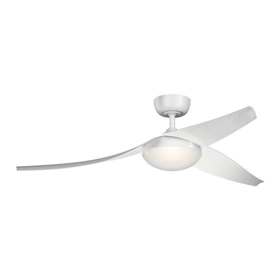
- Page 1 60" FLYY Product images may vary slightly from actual product. INSTRUCTION MANUAL...
-
Page 3: Table Of Contents
TABLE OF CONTENTS SAFETY RULES................4 INSTALLING THE GLASS SHADE........14 TOOLS REQUIRED..............CONTROL SYSTEM SET-UP..........PACKAGE CONTENTS............. BUTTON INSTRUCTION............MOUNTING OPTIONS............. INSTALLING THE WALL CONTROL SYSTEM WALL PLATE............HANGING THE FAN..............OPERATION INSTRUCTIONS..........INSTALLATION OF SAFETY SUPPORT......TROUBLESHOOTING............. ELECTRICAL CONNECTIONS..........FINISHING THE INSTALLATION........ -
Page 4: Safety Rules
SAFETY RULES 1. To reduce the risk of electric shock, insure electricity has been turned 8. Avoid placing objects in the path of the blades. off at the circuit breaker or fuse box before beginning. 9. To avoid personal injury or damage to the fan and other items, be cautious when working around or cleaning the fan. -
Page 5: Tools Required
TOOLS REQUIRED PACKAGE CONTENTS Philips screw driver Unpack your fan and check the Blade screw driver contents. You should have the 11 mm wrench following items: Step ladder Wire cutters a. Fan blades (3) b. Canopy & Ceiling mounting bracket c. -
Page 6: Mounting Options
MOUNTING OPTIONS If there isn't an existing UL (cUL for Canadian Installation) listed mounting box, then read the following instructions. Disconnect the power by removing fuses or turning off circuit breakers. Secure the outlet box directly to the building structure. Use appropriate fasteners and building materials. -
Page 7: Hanging The Fan
HANGING THE FAN REMEMBER to turn off the power before you begin. Hanger bracket To properly install your ceiling fan, follow the steps below. Step 1. Remove the decorative canopy bottom cover from the canopy by turning the cover counter clockwise. (Fig. 5) Ceiling canopy Step 2. - Page 8 HANGING THE FAN (continued) Cross pin Step 5. Remove the hanger ball from the downrod assembly by loosening the set screw, unscrewing and removing removing the cross Hanger pin and unscrewing the ball off the rod. (Fig. 7) ball Set screw Step 6.
- Page 9 HANGING THE FAN (continued) Step 8. Slip the coupling cover, secure ring , canopy cover and canopy Downrod onto the downrod. (Fig. 9) Canopy Slide the secure ring, and fasten using the collar setscrew and Allen Collar setscrew wranch provided. (Fig. 9) Canopy cover Secure ring Thread the hanger ball onto the downrod, insert the cross pin through...
-
Page 10: Installation Of Safety Support
INSTALLATION OF SAFETY SUPPORT (required for Canadian installation ONLY) A safety support cable is provided to help prevent the ceiling fan from falling. Step 1. Attach the provided wood screw and washers to the ceiling joist Ceiling mounting next to the mounting bracket but do not tighten. (Fig. 11) Attach bracket safety cable... -
Page 11: Electrical Connections
ELECTRICAL CONNECTIONS WARNING: Carefully read and retain this Instruction Manual for future reference. WARNING:To avoid possible electrical shock, be sure the electricity is turned off at the main panel by removing the fuse or opening the circuit breaker. WARNING: This control control is designed for use with "DC Motor Ceiling Fans" ONLY. DO NOT use with any other type of electrical appliance. WARNING: All wiring must conform to national and local electrical codes. - Page 12 Ground conductor Black White Yellow Gray White Blue Black Outlet Black RECEIVER Black Black Black Black Green Yellow/green ground White Wall outlet box Black 2P Plug Filter Fig. 13 12 | KICHLER.COM...
-
Page 13: Finishing The Installation
FINISHING THE INSTALLATION Step 1. Tuck all the connections neatly into the ceiling outlet box. Outlet box Step 2. Slide the canopy up to the mounting bracket and place one of the key hole slots over the mounting screw on the mounting bracket. Ceiling Rotate the canopy until the screw head locks in place at the narrow mounting... -
Page 14: Attaching The Fan Blades
ATTACHING THE FAN BLADES Step 1. Align the holes from the blade to the holes from the motor, and secure the blade in place with screws and washers provided. (Fig. 15) Screws Fiber Step 2. Repeat this process to attach the other two blades. Blades washers Fig. -
Page 15: Control System Set-Up
CONTROL SYSTEM SET-UP Press the power button on wall control to TURN THE POWER ON. The LED lights on the wall control will blink thru the power up process, approximately 3 seconds. Green Light Within 60 seconds of powering the unit on, Press and hold the REV/FOR button on the wall control until the light kit blinks twice (or for 5 seconds For/Rev switch if no light kit). -
Page 16: Button Instruction
BUTTON INSTRUCTION LED Indicator Red LED: Transmitter signal indicator. When RF signal is sending, the red light will illuminate. Green LED: To show the Forward and Reverse indicator. ON/OFF button " " ON: Turn on the power. OFF: Turn off the power. Reverse button "... -
Page 17: Installing The Wall Control System Wall Plate
INSTALLING THE WALL CONTROL SYSTEM WALL PLATE Outlet box Select a location to install the Wall Control System Transmitter and Wall Plate. Wall plate Switch REMEMBER also this should state that the control is not to be mounted Screws outdoors. You can safely use the transmitter outdoors but it should be Screws mounted indoors away from excess heat and away from contact with water or humidity. -
Page 18: Operation Instructions
OPERATING INSTRUCTIONS Warm weather - Forward (counter clockwise) A downward airflow creates a cooling effect as shown in Fig. 20. This allows you to set your air conditioner on a warmer setting without affecting your comfort. Cool weather - Reverse (clockwise) An upward airflow moves warm air off the ceiling area as shown in Fig. -
Page 19: Troubleshooting
TROUBLESHOOTING Problem Solution Fan will not start. 1. Check circuit fuses or breakers. 2. Check all electrical connections to insure proper contact. CAUTION: Make sure the main power is OFF when checking any electrical connection. Fan sounds noisy. 1. Make sure all motor housing screws are snug. 2. - Page 20 www.kichler.com KICHLER® LIGHTING 7711 EAST PLEASANT VALLEY ROAD P.O. BOX 318010 CLEVELAND, OHIO 44131-8010 CUSTOMER SERVICE 866.558.5706 8:30 AM TO 5:00 PM EST, MONDAY - FRIDAY...
Need help?
Do you have a question about the FLYY 310700MWH and is the answer not in the manual?
Questions and answers