
Related Manuals for Kichler Lighting Jace LED


Summary of Contents for Kichler Lighting Jace LED
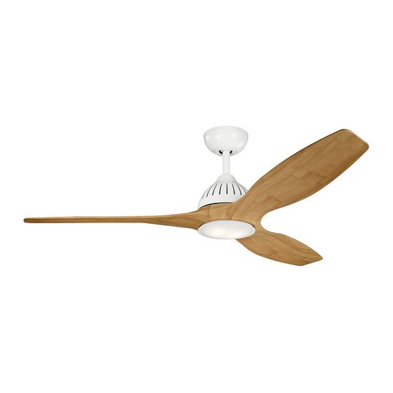
- Page 1 60" JACE LED FAN Product images may vary slightly from actual product. Prod INSTRUCTION MANUAL...
-
Page 3: Table Of Contents
TABLE OF CONTENTS INSTALLING THE LED LIGHT KIT SAFETY RULES................4 AND GLASS SHADE..............15 TOOLS REQUIRED..............INSTALLING THE METAL SHADE ..........PACKAGE CONTENTS............. INSTALLING THE WALL TRANSMITTER ....MOUNTING OPTIONS............. OPERATION INSTRUCTION ..........HANGING THE FAN..............TROUBLESHOOTING............. INSTALLATION OF SAFETY SUPPORT......ELECTRICAL CONNECTIONS.......... -
Page 4: Safety Rules
SAFETY RULES 1. To reduce the risk of electric shock, insure electricity has been 7. Avoid placing objects in the path of the blades. 8. To avoid personal injury or damage to the fan and other items, be cautious when working around or cleaning the fan. 2. -
Page 5: Tools Required
TOOLS REQUIRED PACKAGE CONTENTS Philips screw driver Unpack your fan and check the contents. You should have the Blade screw driver following items: 11 mm wrench Step ladder a. Fan blades (3) Wire cutters b. Canopy & Ceiling mounting bracket c. -
Page 6: Mounting Options
MOUNTING OPTIONS If there isn't an existing UL (cUL for Canadian Installation) listed mounting box, then read the following instructions. Disconnect the Secure the outlet box directly to the building structure. Use appropriate fasteners and building materials. The outlet box and its Outlet box support must be able to fully support the moving weight of the fan (at least 50 lbs). -
Page 7: Hanging The Fan
HANGING THE FAN REMEMBER Hanger bracket To properly install your ceiling fan, follow the steps below. Step 1. Remove the decorative canopy bottom cover from the canopy by turning the cover counter clockwise. (Fig. 5) Ceiling canopy Step 2. Remove the ceiling mounting bracket from the canopy by removing (and save one of the two screws. - Page 8 HANGING THE FAN (continued) Cross pin Step 5. Remove the hanger ball from the downrod assembly by loosening the set screw, unscrewing and removing the cross Hanger ball Set screw Step 6. Loosen the two set screws and remove the hitch pin and retaining clip from the coupling on top of the motor assembly.
- Page 9 HANGING THE FAN (continued) Step 8. Slip the coupling cover , canopy cover and canopy onto the downrod. (Fig. 9) Canopy Thread the hanger ball onto the downrod, insert the cross pin through the downrod and tighten. Now tighten the set screw. (Fig. 9) Canopy cover Step 9.
-
Page 10: Installation Of Safety Support
INSTALLATION OF SAFETY SUPPORT (required for Canadian installation ONLY) A safety support cable is provided to help prevent the ceiling fan from falling. Step 1. Attach the provided wood screw and washers to the ceiling joist Ceiling mounting next to the mounting bracket but do not tighten. (Fig. 11) bracket Attach safety cable... -
Page 11: Electrical Connections
ELECTRICAL CONNECTIONS WARNING: To avoid possible electrical shock, be sure you have turned Receiver Follow the steps below to connect the fan to your household wiring. Hanger bracket Use the wire connecting nuts suppled with your fan. Secure the connectors with electrical tape. Make sure there are no loose wire strands or connections. - Page 12 ELECTRICAL CONNECTIONS (continued) Outlet box Step 2. Motor to Receiver Electrical Connections: (Fig. 13) Connect the White (neutral) Black (hot) black wire from the fan to the black wire marked "TO MOTOR L" on Green or bare the receiver. Connect the white wire from the fan to the white wire copper (ground) Black ("AC IN L") marked "TO MOTOR N"...
-
Page 13: Finishing The Installation
FINISHING THE INSTALLATION Step 1. Tuck all the connections neatly into the ceiling outlet box. Outlet box Step 2. Slide the canopy up to the mounting bracket and place one of the key hole slots over the mounting screw on the mounting bracket. Rotate the canopy until the screw head locks in place at the narrow Ceiling section of the key hole. -
Page 14: Attaching The Fan Blades
ATTACHING THE FAN BLADES Step 1.Align the 4 holes from the blade to the fan motor assembly . Secure the blade with blade screw and metal washer pre-assembled. (Fig.15) Step 2. Follow the same process for the remaining two blades. (Fig.15) Blades metal washer... -
Page 15: And Glass Shade
INSTALLING THE LED ASSEMBLY AND GLASS SHADE NOTE: Before starting installation, disconnect the power by turning Step 1. While holding the LED assembly under your fan, firmly snap Light kit plate the wire connection plugs together.(Fig.17) light kit screw Step 2. Position the LED assembly on the light kit plate and ensure the screw holes are properly aligned.(Fig.17) Step 3. - Page 16 INTALLING THE METAL SHADE Step 1. If you want the fan to be non-light version, please kindly skip step of "installing the LED light kit and glass shade" above and follow the procedure directly : Attach the metal shade to the light kit plate by twisting tightly. (Fig.18) Warning: Before you install the metal shade, please make sure the LED assembly has been disconnected or removed.
-
Page 17: Installing The Wall Transmitter
INSTALLING THE WALL TRANSMITTER FACE PLATE SCREW WARNNING: HOOK UP ‘IN SERIES”ONLY. DO NOT CONNECT NEUTRAL SUPPLY WIRE OF ELECTRIC CIRCUIT TO THE TRANSMITTER WALL SWITCH, DAMAGE TO THE TRANSMITTER WALL SWITCH AND POSSIBLE FIRE COULD OCCUR. Step 1. Remove the existing wall plate and switch from the wall outlet box.(Fig.19) Step 2. -
Page 18: Operation Instruction
OPERATION INSTRUCTION ACTIVATING THE LEARNING PROCESS(Fig.21) faceplate NOTE:The control system for this fan is equipped with a learning frequency function which LEARN has 56K code combinations to prevent potential interference from other remote units. The frequency on your receiver and wall transmitter units have been preset at the factory. No frequency change is necessary. - Page 19 REVERSE FUNCTION NOTE: To change the direction of the rotation of the blades,the fan muse be in operation. Warm weather - Forward (counter clockwise) A downward airflow comfort. Cool weather - Reverse (clockwise) An upward airflow moves warm Fig. 23 Fig.
-
Page 20: Troubleshooting
TROUBLESHOOTING Problem Solution Fan will not start. 1. Check circuit fuses or breakers. 2. Check all electrical connections to insure proper contact. CAUTION: Make sure the main power is OFF when checking any electrical connection. Fan sounds noisy. 1. Make sure all motor housing screws are snug. 2. - Page 21 www.kichler.com KICHLER® LIGHTING 7711 EAST PLEASANT VALLEY ROAD P.O. BOX 318010 CLEVELAND, OHIO 44131-8010 CUSTOMER SERVICE 866.558.5706 8:30 AM TO 5:00 PM EST, MONDAY - FRIDAY...
- Page 22 VENTILADOR CON LED DE 60” JACE™ Las imágenes del producto pueden variar levemente respecto del producto real. MANUAL DE INSTRUCCIONES...
- Page 24 ÍNDICE ACOPLAMIENTO DE LAS ASPAS ....14 NORMAS DE SEGURIDAD......4 INSTALACIÓN DE LA PLACA DE ILUMINACIÓN.
-
Page 25: Normas De Seguridad
NORMAS DE SEGURIDAD 6. Para operar la función inversa en este ventilador, oprima el botón de 1. Para reducir el riesgo de descarga eléctrica, asegúrese de haber sentido inverso mientras el ventilador esté funcionando. cortado el suministro de energía desde el disyuntor o la caja de fusibles antes de comenzar. -
Page 26: Herramientas Requeridas
HERRAMIENTAS REQUERIDAS CONTENIDO DEL ENVASE Destornillador Philips Retire el ventilador de la caja y verifique que Destornillador plano estén todos sus componentes. La caja debería Llave de 11 mm contener los siguientes elementos: Escalera a. Aspas del ventilador (3) Cortacables b. -
Page 27: Opciones De Montaje
OPCIONES DE MONTAJE Si no hay ninguna caja de montaje existente con certificación UL (cUL para instalación en Canadá), entonces lea las siguientes instrucciones. Desconecte el suministro de energía eléctrica retirando los fusibles o apagando los disyuntores. Sujete la caja de distribución directamente a la estructura de la construcción. -
Page 28: Cómo Colgar El Ventilador
CÓMO COLGAR EL VENTILADOR RECUERDE desconectar el suministro de energía eléctrica antes de comenzar con la instalación. Para instalar su ventilador de techo de Soporte colgante manera adecuada, siga los pasos detallados a continuación. Paso 1. Retire la tapa inferior de la cubierta decorativa haciéndola girar en sentido antihorario. - Page 29 CÓMO COLGAR EL VENTILADOR (CONTINUACIÓN) Pasador transversal Paso 5. Retire la bola colgante del ensamblaje del vástago de extensión aflojando el tornillo embutido, desatornillándolo y retirando el pasador Bola transversal y deslizando la bola hasta sacarla del vástago. (Fig. 7) colgante Tornillo embutido Paso 6.
- Page 30 CÓMO COLGAR EL VENTILADOR (CONTINUACIÓN) Paso 8. Deslice la tapa de acoplamiento, la tapa de la cubierta y la cubierta sobre el vástago de extensión. (Fig. 9) Enrosque la bola Cubierta colgante en el vástago de extensión, inserte el pasador transversal en el vástago de extensión y ajuste.
-
Page 31: Instalación Del Soporte De Seguridad
6. INSTALACIÓN DEL SOPORTE DE SEGURIDAD (SE REQUIERE ÚNICAMENTE PARA SU INSTALACIÓN EN CANADÁ) Se incluye un cable de soporte de seguridad que contribuye a evitar que el ventilador de techo se caiga. Paso 1. Inserte el tirafondo y arandelas proporcionados en el colgante Soporte de montaje de viga junto al soporte de montaje, pero no ajuste. -
Page 32: Conexiones Eléctricas
CONEXIONES ELÉCTRICAS ADVERTENCIA: Para evitar posibles descargas eléctricas, asegúrese de haber desconectado el suministro de energía eléctrica desde el panel de circuito principal. Receptor Siga los pasos a continuación para conectar el ventilador al cableado de Soporte colgante su hogar. Utilice las tuercas para cable proporcionadas con el ventilador. Asegure los conectores con cinta aislante. - Page 33 CONEXIONES ELÉCTRICAS Caja de (CONTINUACIÓN) distribución Paso 2. Conexiones eléctricas del motor al receptor: (Fig. 13) Blanco (neutro) Conecte el cable negro del ventilador al cable negro marcado como "TO MOTOR Negro (caliente) Verde o cobre sin L” (AL MOTOR L) del receptor. Conecte el cable blanco del ventilador al cable blanco recubrimiento (a tierra) marcado como "TO MOTOR N”...
-
Page 34: Finalización De La Instalación
FINALIZACIÓN DE LA INSTALACIÓN Paso 1. Inserte las conexiones en forma ordenada dentro de la caja de distribución eléctrica del cielorraso. Caja de distribución Paso 2. Deslice la cubierta hacia arriba hasta el soporte de montaje y coloque una de las ranuras de los orificios principales sobre el tornillo de Soporte de montaje montaje en el soporte de montaje. -
Page 35: Acoplamiento De Las Aspas
ACOPLAMIENTO DE LAS ASPAS Paso 1. Alinee los 2 orificios del aspa con el ensamblaje del motor del ventilador. Asegure el aspa con el tornillo y la arandela de metal preensamblada.(Fig. 15) Paso 2. Repita este proceso para acoplar las otras dos aspas. (Fig. -
Page 36: Y La Pantalla De Vidrio
INSTALACIÓN DEL ENSAMBLAJE DE ILUMINACIÓN LED Y LA PANTALLA DE VIDRIO Placa del kit de NOTA: Antes de comenzar con la instalación, asegúrese de que iluminación la electricidad esté desconectada desde el disyuntor o retire el fusible de la caja de fusibles. Tornillo del kit de iluminación Paso 1. -
Page 37: Instalación De La Pantalla De Metal
INSTALACIÓN DE LA PANTALLA DE METAL Paso 1. Si usted desea no instalar el kit de iluminación en el ventilador, omita el paso de “instalación del kit de iluminación LED y la pantalla de vidrio “ anterior y siga directamente el procedimiento: Acople la pantalla de metal a la placa del kit de iluminación haciéndola girar con fuerza. -
Page 38: Instalación Del Transmisor De Pared
INSTALACIÓN DEL TRANSMISOR DE PARED PLACA FRONTAL TORNILLO ADVERTENCIA: CONECTE ÚNICAMENTE “EN SERIE”. NO CONECTE EL CABLE DE ALIMENTACIÓN BLANCO DEL CIRCUITO ELÉCTRICO CON EL INTERRUPTOR DEL TRANSMISOR DE PARED; SE PODRÍA DAÑAR EL INTERRUPTOR DEL TRANSMISOR DE PARED Y PODRÍA PROVOCARSE UN INCENDIO. Paso 1. -
Page 39: Instrucciones De Funcionamiento
INSTRUCCIONES DE FUNCIONAMIENTO ACTIVACIÓN DEL PROCESO DE OBTENER INFORMACIÓN (FIG. 21) NOTA:El sistema de control del ventilador está equipado con una función de obtener Placa frontal OBTENER información de frecuencia con 56K posibles combinaciones de códigos para evitar la INFORMACIÓN interferencia desde otras unidades remotas. - Page 40 FUNCIÓN DE SENTIDO INVERSO NOTA: Para cambiar el sentido de rotación de las aspas, el ventilador debe estar funcionando. Clima cálido Avance (sentido anti horario) Un flujo de aire descendente crea un efecto de enfriamiento tal como se muestra en la Fig. 23. Esto permite configurar su acondicionador de aire en casos de clima más cálido sin afectar su comodidad.
-
Page 41: Localización Y Resolución De Problemas
LOCALIZACIÓN Y RESOLUCIÓN DE PROBLEMAS Problema Solución El ventilador no arranca. 1. Controle el funcionamiento de los fusibles de circuito o los disyuntores. 2. Verifique todas las conexiones eléctricas para asegurar el debido contacto. PRECAUCIÓN: Asegúrese de que la corriente principal esté DESCONECTADA al verificar cualquier conexión eléctrica 1. - Page 42 www.kichler.com KICHLER® LIGHTING 7711 EAST PLEASANT VALLEY ROAD P.O. BOX 318010 CLEVELAND, OHIO 44131-8010 SERVICIO DE ATENCIÓN AL CLIENTE 866.558.5706 8:30 AM A 5:00 PM HORA DEL ESTE, DE LUNES A VIERNES...
- Page 43 VENTILATEUR À LED JACE™ 60 po Le produit peut différer légèrement des illustrations. MANUEL D’INSTRUCTIONS...
- Page 45 TABLE DES MATIÈRES FIXATION DES PALES DE VENTILATEUR....14 CONSIGNES DE SÉCURITÉ......4 INSTALLATION DE LA PLAQUE D’ÉCLAIRAGE.
-
Page 46: Consignes De Sécurité
CONSIGNES DE SÉCURITÉ 6. Pour utiliser la fonction inverse sur ce ventilateur, appuyer sur le 1. Pour réduire le risque d'électrocution, assurez-vous que l'électricité a bouton de marche arrière pendant que le ventilateur est en marche. été coupée au niveau du disjoncteur ou de la boîte à fusibles avant de commencer. -
Page 47: Outillage Requis
OUTILLAGE REQUIS CONTENU DE L’EMBALLAGE Tournevis Philips Déballez votre ventilateur et vérifiez le contenu. Tournevis standard Pale Vous devriez avoir à votre disposition Clé de 11 mm les éléments suivants : Escabeau a. Pales de ventilateur (3) Coupe-fil b. Cache et support de montage au plafond c. -
Page 48: Options De Montage
OPTIONS DE MONTAGE En l'absence d'une boîte de montage homologuée cUL (UL pour les États-Unis), prendre connaissance des instructions suivantes. Débrancher l'alimentation en retirant les fusibles ou en déclenchant les disjoncteurs de la boîte à prises. Fixer la boîte à prises directement sur la structure du bâtiment. Utiliser des attaches et des matériaux de construction appropriés. -
Page 49: Suspension Du Ventilateur
SUSPENSION DU VENTILATEUR RAPPEL Attache de suspension Pour installer correctement votre ventilateur de plafond, procéder comme suit. Cache au Étape 1. Retirez le couvercle du fond du cache décoratif en le tournant dans le sens antihoraire (Fig. 5). plafond Étape 2. Retirez le support de fixation au plafond du cache en le enlevant Couvercle (et en mettant de côté) une des deux vis. - Page 50 SUSPENSION DU VENTILATEUR (SUITE) Goupille transversale Étape 5. Retirez la boule de suspension de la tige de fixation en desserrant la vis de blocage, en dévissant et en retirant la goupille transversale et en Boule de retirant la boule de la tige (Fig. 7). suspension Vis de pression Étape 6.
- Page 51 SUSPENSION DU VENTILATEUR (SUITE) Étape 8. Faites glisser le couvercle d'accouplement, le couvercle du cache et le cache sur la tige de suspension. (Fig. 9). Placez la balle de Cache suspension sur la tige de suspension, insérez la broche transversale dans la tige de suspension et serrez.
-
Page 52: Installation Du Support De Sécurité
INSTALLATION DU SUPPORT DE SÉCURITÉ (requis UNIQUEMENT dans le cas d'une installation canadienne) Un câble de support de sécurité est fourni pour empêcher que le ventilateur de plafond ne tombe. Étape 1. Fixez la vis à bois et les rondelles fournies à la solive du plafond à Support de montage côté... -
Page 53: Connexions Électriques
CONNEXIONS ÉLECTRIQUES AVERTISSEMENT: Pour éviter tout risque d'électrocution, s'assurer que l'alimentation est coupée au niveau du panneau de circuit principal. Récepteur Procédez comme suit pour raccorder le ventilateur au câblage du Support de suspension domicile. Utilisez les raccords de connexion des fils fournis avec le ventilateur. - Page 54 CONNEXIONS ÉLECTRIQUES Boîte à prises (SUITE) Étape 2. Connexions électriques entre le moteur et le récepteur : (Fig. 13) Blanc (neutre) Noir (sous tension) Vert ou cuivre nu (terre) Connectez le fil NOIR du ventilateur au fil noir marqué "TO MOTOR L" du récepteur. Connectez le fil blanc du ventilateur au fil blanc marqué...
-
Page 55: Fin De L'installation
FIN DE L'INSTALLATION Étape 1. Placez toutes les connexions parfaitement dans la boîte à prises du plafond. Boîte à prises Étape 2. Faites glisser le cache jusqu'au support de montage et placez l'une des principales fentes de trou au-dessus de la vis de montage sur Support de le support de montage. - Page 56 FIXER LES PALES DU VENTILATEUR Étape 1. Alignez les 4 trous de la pale sur le moteur du ventilateur. Fixez la pale avec la vis et la rondelle en métal pré-assemblées prévue pour les pales. (Fig. 15) Étape 2. Suivez le même processus pour les deux autres pales. (Fig. 15) Pales Rondelle en métal Vis pour pale...
-
Page 57: Cache En Verre
INSTALLATION DE L'ENSEMBLE LED ET DU CACHE EN VERRE Plaque du REMARQUE: Avant de commencer l’installation, débrancher d’éclairage l'alimentation en déclenchant le disjoncteur ou en retirant le fusible de la boîte à fusibles. Vis de la plaque du kit d'éclairage Étape 1. -
Page 58: Installation Du Cache En Metal
INSTALLATION DU CACHE EN MÉTAL Étape 1. Pour faire tourner le ventilateur sans l'éclairage, passez l'étape ci-dessus Installation du kit d'éclairage à LED et du cache en verre ci-dessus et procédez comme suit : Fixez le cache en métal sur la plaque du kit d’éclairage en le tournant fermement (Fig. -
Page 59: Installation De L'émetteur Mural
INSTALLATION DE L’ÉMETTEUR MURAL PLAQUE AVANT AVERTISSEMENT: RELIER 'EN SÉRIE' UNIQUEMENT. NE PAS CONNECTER DE FIL D'ALIMENTATION NEUTRE DU CIRCUIT ÉLECTRIQUE À L’INTERUPTEUR MURAL DE L'ÉMETTEUR MURAL SOUS RISQUE D'ENDOMMAGER L'INTERRUPTEUR MURAL ET DÉCLENCHER UN INCENDIE. Étape 1. Retirez la plaque murale présente et l'ancien interrupteur de la boîte à... -
Page 60: Instructions D'utilisation
INSTRUCTIONS D’UTILISATION ACTIVATION DU PROCESSUS D'APPRENTISSAGE (Fig.21) Plaque avant REMARQUE: Le système de contrôle de ce ventilateur est équipé d’une fonction de LEARN fréquence d’apprentissage dotée de combinaisons de 56K codes afin d’empêcher toute (APPRENTISSAGE) interférence provenant d’autres télécommandes. La fréquence du récepteur et de l'émetteur mural a été... - Page 61 FONCTION EN MARCHE ARRIÈRE REMARQUE: Pour changer le sens de rotation des pales, le ventilateur doit être en marche. Temps chaud - Vers l'avant (sens inverse des aiguilles d'une montre) Un flux d'air confortable vers le bas. Temps frais - En marche arrière (dans le sens des aiguilles d'une montre) Un flux d'air chaud vers le haut.
-
Page 62: Dépannage
DÉPANNAGE Problème Solution Impossible de mettre le 1. Vérifiez les fusibles ou disjoncteurs de circuit. ventilateur en marche. 2. Vérifiez tous les raccordements électriques pour garantit un bon contact. MISE EN GARDE : Assurez-vous que l'alimentation principale est COUPÉE lors de la vérification des raccordements électriques. - Page 63 www.kichler.com KICHLER® LIGHTING 7711 EAST PLEASANT VALLEY ROAD P.O. BOX 318010 CLEVELAND, OHIO 44131-8010 U.S.A. SERVICE À LA CLIENTÈLE 866.558.5706 De 08h30 à 17h (heure normale du l'Est), du lundi au vendredi...
Need help?
Do you have a question about the Jace LED and is the answer not in the manual?
Questions and answers