
Related Manuals for Kichler Lighting True


Summary of Contents for Kichler Lighting True
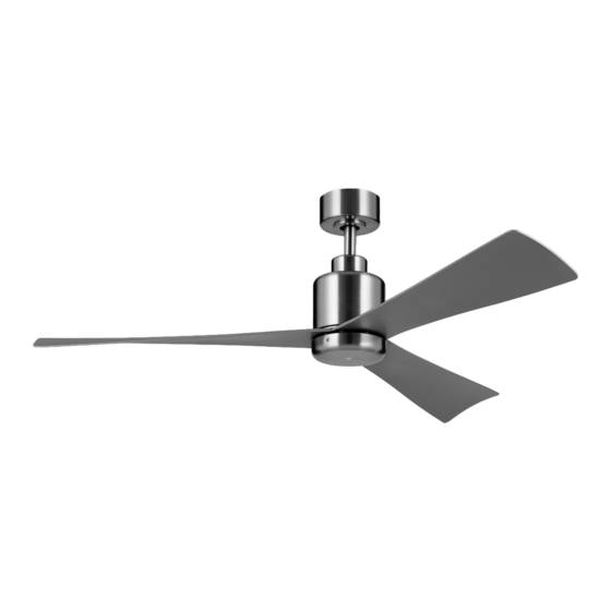
- Page 1 52" True Product images may vary slightly from actual product. INSTRUCTION MANUAL Model# 310452 READ AND SAVE THESE INSTRUCTIONS...
-
Page 2: Table Of Contents
TABLE OF CONTENTS SAFETY RULES ................3 INSTALLING THE FAN BLADES ..........14 TOOLS AND MATERIALS REQUIRED ........5 INSTALLING THE DECORATIVE COVER.......14 PACKAGE CONTENTS ..............5 INSTALLING THE COOLTOUCH™ WALL PLATE ....15 MOUNTING OPTIONS ..............6 INSTALLING THE TRANSMITTER ..........15 HANGING THE FAN ..............7 OPERATING INSTRUCTIONS ..........16 INSTALLATION OF SAFETY CABLE ........ -
Page 3: Safety Rules
10. WARNING: make sure the power is disconnected outlet box. Most outlet boxes commonly used for before cleaning your fan. the support of light fixtures are not acceptable for 52" True | 3... - Page 4 SAFETY RULES (continued) 11. To avoid personal injury or damage to the fan and 16. N.W. 7.82 KGS (17.24 LBS) / G.W. 8.75 KGS (19.29 LBS) other items, be cautious when working around or cleaning the fan. 12. Do not use water or detergents when cleaning the fan WARNING or fan blades.
-
Page 5: Tools And Materials Required
2) Blade Attachment Hardware: E. Fan Motor Assembly Blade Screws (11), Fiber Washers (11) F. Decorative Cover 3) Safety Cable Hardware: G. Receiver Wood Screw (1), Flat Washer (1) H. Transmitter (371075) and Wall Plate 4) Balance Kit 52" True | 5... -
Page 6: Mounting Options
MOUNTING OPTIONS If there is not an existing UL (cUL for Canadian Installation) listed mounting box, then read the following instructions. Disconnect the power by removing fuses or turning off circuit breakers. Secure the outlet box directly to the building structure. Use Outlet box appropriate fasteners and building materials. -
Page 7: Hanging The Fan
Step 4. Attach the ceiling mounting bracket to the outlet box using the (Supplied with Mounting Screw Electrical Box) screws and washers included with the outlet box. (Fig. 6) 120V Wires (Supplied with Electrical Box) Fig. 6 52" True | 7... - Page 8 HANGING THE FAN (continued) Ball WARNING: All set screws must be checked, and retightened where Ball Cross Pin necessary, before installation. Cross Step 5. Remove the retaining clip and the hitch pin from the ball/downrod Set Screw assembly. Remove the ball from the ball/downrod assembly by loosening the set Set Screw Downrod screw (do not remove) on the ball, unscrewing and removing the cross pin, and...
- Page 9 WARNING: Failure to reattach the cross pin and seat the “Check Tab” can cause the fan to fall from the ceiling during operation. Take Registration Slot special care to make sure this pin is reattached. Fig. 10 52" True | 9...
-
Page 10: Installation Of Safety Cable
INSTALLATION OF SAFETY Cable (required for Canadian installation ONLY) A safety support cable is provided to help prevent the ceiling fan from falling, please Ceiling Mounting install it as follows. Bracket Attach safety cable Step 1. Attach the wood screw and washer to the ceiling joist next to the ceiling to ceiling joist with wood screw and washer mounting bracket but do not tighten. - Page 11 Separate the white (neutral) and green (ground) wire connections to the one side of the outlet box, and the black (hot) wire connections to the other side of the outlet box. 52" True | 11...
- Page 12 ELECTRICAL CONNECTIONS (continued) A. CEILING FAN TO RECEIVER WIRE CONNECTION Step 1. Connect the Blue wire from the fan (motor) to the Blue wire from the receiver. White wire from the fan (motor) to the White wire from the GROUND BLACK WHITE CONDUCTOR receiver.
-
Page 13: Finishing The Motor Installation
Failure to properly seat the “Check Tab” could damage the electrical wires when ceiling fan blade direction is changed while the fan is running. 52" True | 13... -
Page 14: Installing The Fan Blades
INSTALLING THE FAN BLADES CAUTION: To reduce the risk of electric shock, disconnect Blade the electrical supply circuit to the fan before installing fan Screws blades. Hole Step 1. Align the holes in the fan blade with the holes in the motor assembly, and secure the fan blade to the motor assembly with the Motor fiber washers and blade screws provided. -
Page 15: Installing The Cool Touch Wall Plate
(Fig. 19) Step 2. To remove the transmitter from the wall plate, push the release button and the Fig. 19 transmitter will fall into your hand. 52" True | 15... -
Page 16: Operating Instructions
OPERATING INSTRUCTIONS Safety Screw INSTALLING THE TRANSMITTER BATTERIES (Fig. 20) Back Cover Step 1. Remove the back cover of the transmitter and safety screw. (Fig. 20) Install two CR2032 3V batteries (included) with the+ side facing up. NOTE: To prevent damage to the transmitter, remove the batteries if not in use Batteries for long periods of time (several months). - Page 17 Step 2 again. Step 4. Reinstall the battery cover and safety screw to the back of the transmitter. NOTE: Please keep this page in case future reprogramming is needed, or an additional remote control is added. 52" True | 17...
- Page 18 OPERATING INSTRUCTIONS (continued) TRANSMITTER OPERATION (Fig. 22) OFF Button Press once to stop the fan. Fan speed control buttons 1 is the lowest speed and 6 is the highest speed. Press one of the buttons to start the fan at the corresponding speed, or to change speeds.
-
Page 19: Troubleshooting
6. Do not connect this fan to wall mounted variable speed control(s). They are not compatible with ceiling fan motors or remote controls. 7. Make sure the upper canopy is a short distance from the ceiling. It should not touch the ceiling. 52" True | 19... - Page 20 TROUBLESHOOTING (continued) Problem Solution Solution Fan wobble. 1. Check that all blade and blade arm screws are secure. 2. Most fan wobbling problems are caused when blade levels are unequal. Check this level by selecting a point on the ceiling above the tip of one of the blades. Measure this distance. Rotate the fan until the next blade is positioned for measurement.
-
Page 21: Fcc Information
• Increase the separation between the equipment and receiver. • Connect the equipment into an outlet on a circuit different from that to which the receiver is connected. • Consult the dealer or an experienced radio/TV technician for help. 52" True | 21... - Page 22 KICHLER LIGHTING LLC 30455 SOLON RD. SOLON, OH 44139 USA CUSTOMER SERVICE 866.558.5706 8:00 AM TO 5:00 PM EST, MONDAY - FRIDAY REV. 6-NOV-2023 © Kichler Lighting LLC. All Rights Reserved.
- Page 23 True 52 po Les images du produit peuvent varier légèrement par rapport au produit réel. MANUEL D’INSTRUCTIONS Modèle n° 310452 LISEZ ET CONSERVEZ CES INSTRUCTIONS...
- Page 24 TABLE DES MATIÈRES RÈGLES DE SÉCURITÉ .............. 3 INSTALLATION DES PALES DU VENTILATEUR ....14 OUTILS ET MATÉRIAUX NÉCESSAIRES ........ 5 INSTALLATION DU COUVERCLE DÉCORATIF....14 CONTENU DU COLIS ..............5 INSTALLATION DE LA PLAQUE MURALE COOLTOUCH™ ............15 OPTIONS DE MONTAGE ............6 INSTALLATION DE L’ÉMETTEUR ...........15 SUSPENDRE LE VENTILATEUR ..........7 INSTRUCTIONS D’UTILISATION ..........16...
-
Page 25: Règles De Sécurité
9. Évitez de placer des objets sur la trajectoire des pales. (35 lb) ou moins ». Utilisez les vis de montage livrées 10. AVERTISSEMENT : assurez-vous que l’alimentation avec la boîte de sortie. Il faudra probablement est coupée avant de nettoyer votre ventilateur. True 52 po | 3... - Page 26 RÈGLES DE SÉCURITÉ (suite) 11. Pour éviter des blessures corporelles ou des 16. PDS N 7,82 KG (17,24 LB) / PDS B 8,75 KG (19,29 LB) dommages au ventilateur et à d’autres éléments, soyez prudent lorsque vous travaillez autour ou nettoyez le ventilateur.
-
Page 27: Outils Et Matériaux Nécessaires
Vis de pale (11), Rondelles de fibre (11) F. Couvercle décoratif 3) Matériel du câble de sécurité : G. Récepteur Vis à bois (1), Rondelle à ressort (1) H. Émetteur (371075) et plaque murale 4) Trousse d’équilibre True 52 po | 5... -
Page 28: Options De Montage
OPTIONS DE MONTAGE S’il n’y a pas de boîtier de montage homologué UL (cUL pour installation canadienne), lisez les instructions suivantes. Débranchez l’alimentation en retirant les fusibles ou en désactivant les disjoncteurs. Boîtier de sortie Fixez le boîtier de sortie directement à la structure du bâtiment. Utilisez des fixations et des matériaux de construction Image 1 appropriés. -
Page 29: Suspendre Le Ventilateur
(fournie avec le coffret électrique) Étape 4. Installez le support de montage sur le boîtier de sortie au plafond à Image 6 l’aide des vis et rondelles fournies avec le boîtier de sortie. (Image 6) True 52 po | 7... - Page 30 SUSPENDRE LE VENTILATEUR (Suite) Boule AVERTISSEMENT : Toutes les vis de réglage doivent être vérifiées et Boule Broche croisée resserrées si nécessaire avant l’installation. Broche croisée Étape 5. Retirez le clip de retenue et la goupille d’attelage de l’ensemble boule/ Vis de réglage tige descendante.
- Page 31 « languette de contrôle » peut entraîner la chute du ventilateur du plafond pendant le fonctionnement. Veillez tout Image 10 particulièrement à ce que cette goupille soit remise en place. True 52 po | 9...
-
Page 32: Installation Du Câble De Sécurité
INSTALLATION DU CÂBLE DE SÉCURITÉ (requis pour l’installation au Canada SEULEMENT) Un câble de support de sécurité est fourni pour aider à empêcher le ventilateur de Support de montage plafond de tomber, veuillez l’installer comme suit. au plafond Fixez le câble de sécurité Étape 1. - Page 33 Séparez les raccordements de fil blanc (neutre) et vert (mise à la terre) d’un côté du boîtier de sortie et les raccordements de fil noir (sous tension) de l’autre côté. True 52 po | 11...
- Page 34 RACCORDEMENTS ÉLECTRIQUES (SUITE) A. CONNEXION DES FILS DU VENTILATEUR DE PLAFOND AU RÉCEPTEUR Étape 1. Raccordez le fil bleu du ventilateur (moteur) au fil bleu du CONDUCTEUR NOIR BLANC DE TERRE récepteur; le fil blanc du ventilateur (moteur) au fil blanc du récepteur; JAUNE le fil rouge du ventilateur (moteur) au fil rouge du récepteur;...
-
Page 35: Finition De L'installation Du Moteur
Si vous ne placez pas correctement la « languette de contrôle », vous risquez d’endommager les fils électriques lorsque vous changez la direction des pales du ventilateur de plafond pendant que le ventilateur fonctionne. True 52 po | 13... -
Page 36: Installation Des Pales Du Ventilateur
INSTALLATION DES PALES DU VENTILATEUR Vis de pale ATTENTION : Pour réduire le risque d’électrocution, débranchez le circuit d’alimentation électrique du ventilateur avant d’installer les pales du ventilateur. Trou Étape 1. Alignez les trous de la pale du ventilateur avec les trous de Assemblage du moteur l’ensemble moteur et fixez la pale du ventilateur à... -
Page 37: Installation De La Plaque Murale Cooltouch
(Image 19) Étape 2. Pour retirer l’émetteur de la plaque murale, appuyez sur le bouton de déverrouillage et Image 19 l’émetteur tombera dans votre main. True 52 po | 15... -
Page 38: Instructions D'utilisation
INSTRUCTIONS D’UTILISATION Vis de sécurité INSTALLATION DES PILES DE L’ÉMETTEUR (Image 20) Couvercle arrière Étape 1. Retirez le couvercle arrière de l’émetteur et la vis de sécurité. (Image 20) Installez deux piles 3V CR2032 (incluses) avec le côté + vers le haut. REMARQUE : Pour éviter d’endommager l’émetteur, retirez les piles si vous ne l’utilisez Piles pas pendant une longue période (plusieurs mois). - Page 39 Étape 4. Réinstallez le couvercle du boîtier de la pile et la vis de sécurité sur l’arrière de l’émetteur. REMARQUE : Veuillez conserver cette page au cas où une reprogrammation serait nécessaire à l’avenir ou si une télécommande supplémentaire est ajoutée. True 52 po | 17...
- Page 40 MODE D’EMPLOI (SUITE) FONCTIONNEMENT DE L’ÉMETTEUR (Image 22) Bouton ARRÊT Appuyer une fois pour arrêter le ventilateur. Boutons de contrôle de la vitesse du ventilateur 1 est la vitesse la plus faible et 6 est la vitesse la plus élevée. Appuyez sur l’un des boutons pour démarrer le ventilateur à...
-
Page 41: Dépannage
6. Ne connectez pas ce ventilateur à une ou plusieurs commandes de vitesse variable fixées au mur. Ils ne sont pas compatibles avec les moteurs de ventilateurs de plafond ou les télécommandes. 7. Assurez-vous que l’auvent supérieur est à une courte distance du plafond. Elle ne doit pas toucher le plafond. True 52 po | 19... - Page 42 DÉPANNAGE (suite) Problème Solution Solution Le ventilateur 1. Vérifiez que toutes les vis de la pale et du bras de pale sont bien fixées. vacille. 2. La plupart des problèmes d’oscillation du ventilateur sont causés lorsque les niveaux des pales sont inégaux. Vérifiez ce niveau en sélectionnant un point sur le plafond au-dessus de la pointe de l’une des pales.
-
Page 43: Informations Fcc
• Augmentez l’espace entre l’équipement et le récepteur. • Branchez l’équipement à une prise sur un circuit différent de celui auquel le récepteur est raccordé. • Consultez le revendeur ou un technicien radio/TV expérimenté pour obtenir de l’aide. True 52 po | 21... - Page 44 KICHLER LIGHTING LLC 30455 SOLON RD. SOLON, OHIO 44139 USA SERVICE À LA CLIENTÈLE 866.558.5706 8 h à 17 h EST, DU LUNDI AU VENDREDI RÉV. 6-NOV-2023 © Kichler Lighting LLC. Tous droits réservés.
- Page 45 True de 1.32 m (52 in) Las imágenes del producto pueden diferir ligeramente del producto real. MANUAL DE INSTRUCCIONES Número de modelo 310452 LEA Y GUARDE ESTAS INSTRUCCIONES...
- Page 46 ÍNDICE NORMAS DE SEGURIDAD..............3 INSTALACIÓN DE LAS ASPAS DEL VENTILADOR ....14 HERRAMIENTAS Y MATERIALES REQUERIDOS ....5 INSTALACIÓN DE LA TAPA DECORATIVA........ 14 CONTENIDO DEL PAQUETE ............5 INSTALACIÓN DE LA PLACA DE PARED COOLTOUCH™ ..15 OPCIONES DE MONTAJE ..............6 INSTALACIÓN DEL TRANSMISOR ..........
-
Page 47: Normas De Seguridad
10. ADVERTENCIA: asegúrese de que la corriente esté para soporte de ventilador de 15.9 kg (35 lb) o menos” y desconectada antes de limpiar el ventilador. use los tornillos de montaje proporcionados con la caja True de 1.32 m (52 in) | 3... - Page 48 NORMAS DE SEGURIDAD (continuación) 11. Para evitar lesiones personales o daños al ventilador 16. Peso neto: 7.82 KG (17.24 LB)/peso bruto: 8.75 KG (19.29 LB) y otros elementos, tenga cuidado cuando trabaje alrededor del ventilador o cuando lo limpie. ADVERTENCIA 12.
-
Page 49: Herramientas Y Materiales Requeridos
Tornillos de aspa (11), Arandelas de fibra (11) F. Tapa decorativa 3) Accesorios del cable de seguridad: G. Receptor Tornillo para madera (1), Arandela plana (1) H. Transmisor (371075) y placa de pared 4) Kit de balanceo True de 1.32 m (52 in) | 5... -
Page 50: Opciones De Montaje
OPCIONES DE MONTAJE Si no existe una caja de montaje con certificación UL (cUL para la instalación en Canadá), lea las siguientes instrucciones. Desconecte la energía quitando los fusibles o apagando los disyuntores. Caja de salida Fije la caja de salida directamente a la estructura del edificio. Utilice sujetadores y materiales de construcción adecuados. -
Page 51: Cómo Colgar El Ventilador
Paso 4. Fije el soporte de montaje del techo a la caja de salida usando los Figura 6 tornillos y las arandelas incluidos con la caja de salida. (Figura 6) True de 1.32 m (52 in) | 7... - Page 52 CÓMO COLGAR EL VENTILADOR (continuación) Bola ADVERTENCIA: Todos los tornillos de fijación deben revisarse y Bola Pasador volverse a apretar cuando sea necesario antes de la instalación. transversal Pasador Paso 5. Retire el clip de retención y el pasador de enganche del conjunto de bola/ transversal Tornillo de fijación varilla de extensión.
- Page 53 ADVERTENCIA: Si no vuelve a colocar el pasador transversal y asienta la “lengüeta de retención”, el ventilador puede caerse del techo durante el funcionamiento. Tenga especial cuidado Figura 10 para asegurarse de que este pasador se vuelva a colocar. True de 1.32 m (52 in) | 9...
-
Page 54: Instalación Del Cable De Seguridad
INSTALACIÓN DEL CABLE DE SEGURIDAD (ÚNICAMENTE es necesario para la instalación en Canadá) Soporte de montaje en el techo Se proporciona un cable de soporte de seguridad para ayudar a evitar que el Fije el cable de seguridad a la ventilador de techo se caiga;... - Page 55 Separe las conexiones de los cables blanco (neutro) y verde (conexión a tierra) a un lado de la caja de salida, y las conexiones de cable negro (corriente) al otro lado de la caja de salida. True de 1.32 m (52 in) | 11...
- Page 56 CONEXIONES ELÉCTRICAS (continuación) A. CONEXIÓN DEL VENTILADOR DE TECHO AL CABLE RECEPTOR Paso 1. Conecte el cable azul del ventilador (motor) al cable azul del receptor. Conecte el cable blanco del ventilador (motor) al cable blanco CONDUCTOR NEGRO BLANCO DE TIERRA del receptor.
-
Page 57: Finalización De La Instalación Del Motor
Si la “lengüeta de retención” no se asienta correctamente, se podrían dañar los cables eléctricos cuando se cambia la dirección del aspa del ventilador de techo mientras el ventilador está en funcionamiento. True de 1.32 m (52 in) | 13... -
Page 58: Instalación De Las Aspas Del Ventilador
INSTALACIÓN DE LAS ASPAS DEL VENTILADOR Tornillos de aspa PRECAUCIÓN: Para reducir el riesgo de descarga eléctrica, desconecte el circuito de suministro eléctrico al ventilador antes de instalar las aspas. Orificio Paso 1. Alinee los orificios del aspa del ventilador con los orificios del Conjunto conjunto del motor y asegure el aspa del ventilador al conjunto del del motor... -
Page 59: Instalación De La Placa De Pared Cooltouch
(Figura 19) Paso 2. Para quitar el transmisor de la placa de pared, presione el botón de liberación y el Figura 19 transmisor le caerá en la mano. True de 1.32 m (52 in) | 15... -
Page 60: Instrucciones De Funcionamiento
INSTRUCCIONES DE FUNCIONAMIENTO Tornillo de seguridad INSTALACIÓN DE LAS BATERÍAS DEL TRANSMISOR (Figura 20) Cubierta posterior Paso 1. Retire el tornillo de seguridad y la cubierta de la parte posterior del transmisor. (Figura 20) Instale dos baterías CR2032 de 3 V (incluidas) con el lado + orientado hacia arriba. - Page 61 Paso 4. Vuelva a instalar la cubierta de la batería y el tornillo de seguridad en la parte posterior del transmisor. NOTA: Conserve esta página en caso de que se necesite una reprogramación futura o se agregue un control remoto adicional. True de 1.32 m (52 in) | 17...
- Page 62 INSTRUCCIONES DE FUNCIONAMIENTO (continuación) FUNCIONAMIENTO DEL TRANSMISOR (Figura 22) Botón APAGAR Presiónelo una vez para detener el ventilador. Botones de control de velocidad del ventilador 1 es la velocidad más baja y 6 es la velocidad más alta. Presione uno de los botones para encender el ventilador a la velocidad correspondiente o para cambiar de velocidad.
-
Page 63: Resolución De Problemas
6. No conecte este ventilador a controles de velocidad variable montados en la pared. No son compatibles con motores de ventiladores de techo o controles remotos. 7. Asegúrese de que el florón superior esté a poca distancia del techo. No debe tocar el techo. True de 1.32 m (52 in) | 19... - Page 64 RESOLUCIÓN DE PROBLEMAS (continuación) Problema Solución Solución El ventilador 1. Verifique que todas las aspas y los tornillos de los brazos de las aspas estén firmes. presenta 2. La mayoría de los problemas de oscilación del ventilador se deben a que los niveles de las aspas no son iguales. oscilación.
-
Page 65: Información De La Fcc
• Conectar el equipo a una toma de corriente en un circuito diferente al que está conectado el receptor. • Consulte con el distribuidor o con un técnico de radio/TV experimentado para obtener ayuda. True de 1.32 m (52 in) | 21... - Page 66 KICHLER LIGHTING LLC 30455 SOLON RD. SOLON, OH 44139, EE. UU. SERVICIO AL CLIENTE 866.558.5706 8:00 A. M. A 5:00 P. M. EST, DE LUNES A VIERNES REV. 6-NOV-2023 © Kichler Lighting LLC. Todos los derechos reservados.
Need help?
Do you have a question about the True and is the answer not in the manual?
Questions and answers