
Related Manuals for Kichler Lighting 310155


Summary of Contents for Kichler Lighting 310155
- Page 1 Kichler ® Lighting 7711 East Pleasant Valley Road P.O. Box 318010 Cleveland, Ohio 44131-8010 Customer Service 866.558.5706 8:30 AM to 5:00 PM EST, Monday - Friday...
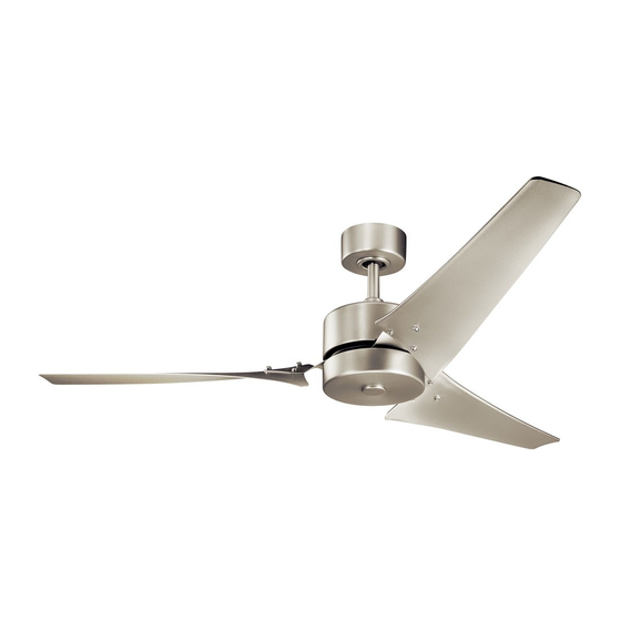
- Page 2 Rana 310155 Instruction Manual UL Model # 60-RECI...
-
Page 3: Safety Rules
1. SAFETY RULES 1. To reduce the risk of electric shock, insure 9. To avoid personal injury or damage to the fan electricity has been turned off at the circuit and other items, be cautious when working breaker or fuse box before beginning. around or cleaning the fan. - Page 4 60” Rana ™ 2. TOOLS AND MATERIALS REQUIRED • Phillips screw driver • Blade screw driver • 11mm wrench • Step ladder • Wire cutters 3. PACKAGE CONTENTS Unpack your fan and check the contents. You should have the following items: Fan blade/blade arm assemblies (3) Ceiling mounting bracket, Canopy and Canopy bottom cover...
-
Page 5: Mounting Options
4. MOUNTING OPTIONS If there isn’t an existing UL (cUL for Canadian Installation) listed mounting box, then read the following instructions. Disconnect the power by removing fuses or turning off circuit breakers. Secure the outlet box directly to the building structure. Outlet box Use appropriate fasteners and building materials. - Page 6 60” Rana ™ 5. HANGING THE FAN REMEMBER to turn off the power before you begin. Canopy To properly install your ceiling fan, follow the steps below. Step 1. Remove the decorative canopy bottom Canopy cover cover from the canopy by turning the cover counterclockwise.
- Page 7 Supply wires & Safety cable Step 7. Loosen the two setscrews and remove the Downrod hitch pin and retaining clip from the coupling on top Coupling of the motor assembly. (Fig. 9) Set screw Set screw Step 8. Carefully route the electrical supply wires and safety cable exiting the top of the fan Hitch Retaining...
- Page 8 60” Rana ™ 6. INSTALLATION OF SAFETY SUPPORT (Required for Canadian installation ONLY) A safety support cable is provided to help prevent the ceiling fan from falling, please install it as follows. Step 1. Attach the provided wood screw and washers to the ceiling joist next to the mounting bracket but do not tighten.
-
Page 9: Finishing The Installation
Connect the white wire from the fan to the white wire marked ”TO MOTOR N” from the receiver. Connect the Outlet box blue wire from the fan to the blue wire marked ”FOR White (neutral) Black (hot) LIGHT” from receiver. Secure all the wire connections with Green or bare copper (ground) the plastic wire nuts provided. - Page 10 60” Rana ™ 9. ATTACHING THE FAN BLADE/ BLADE ARM ASSEMBLIES Attach each blade assembly to the motor by using two mounting screws for each blade assembly. (Fig. 17) Blade Blade arm NOTE : Make sure these mounting screws are securely tightened.
- Page 11 11. INSTALLING THE LIGHT KIT FITTER ASSEMBLY Step 1. Remove one screw from the light kit pan, and loosen, but do not remove the other two screws. (Fig. 20) Step 2. Connect the blue wire exiting the bottom of fan motor assembly with the black wire from the top of the light kit fitter assembly.
- Page 12 60” Rana ™ 13. INSTALLING THE BATTERIES Remove the face plate of the Wall Switch by lifting at the top and then inserting the supplied 12V battery. Duracell MN21/Eveready A23/ GP 23A all 12V. Replace the switch face plate. FAN OFF ON ECE 1 2 3 4 To prevent possible damage to the transmitter,...
- Page 13 15. INSTALLING THE BASIC FUNCTION Outlet box WALL CONTROL SYSTEM WALL Switch PLATE Wall plate Select a location to install the Basic Function Wall Control System Transmitter and Wall Plate. REMEMBER you can safely use the transmitter outdoors but it should be mounted indoors away from contact with water or humidity.
-
Page 14: Operating Instructions
60” Rana ™ 16. OPERATING INSTRUCTIONS The Black Slide Switch on the side of the switch housing controls the direction of the blades “Forward and Reverse”. Warm weather - Forward (counter clockwise). A downward airflow creates a cooling effect as shown in Fig. -
Page 15: Troubleshooting
17. TROUBLESHOOTING Problem Solution Fan will not start. 1. Check circuit fuses or breakers. 2. Check all electrical connections to insure proper contact. CAUTION: Make sure the main power is OFF when checking any electrical connection. 3. Make sure the transmitter batteries are installed properly. Positive (+) side facing out. 4. - Page 16 This device complies with Part 15 of the FCC rules. Operation is subject to the following two conditions: 1) this device may not cause harmful interference, and 2) this device must accept any interference received, including interference that may cause undesired operation. Note: This equipment has been tested and found to comply with the limits for a Class B digital device, pursuant to part 15 of the FCC Rules.
Need help?
Do you have a question about the 310155 and is the answer not in the manual?
Questions and answers