Table of Contents
Advertisement
Quick Links
Kichler
®
Lighting
7711 East Pleasant Valley Road
P.O. Box 318010
Cleveland, Ohio 44131-8010
Customer Service
866.558.5706
8:30 AM to 5:00 PM EST,
Monday - Friday
I
Includes our new
C
CoolTouch
6 Speed DC Control System
TM
L
Looks permanent, but goes wherever you go!
U
U.S. Patent Pending
Instruction Manual
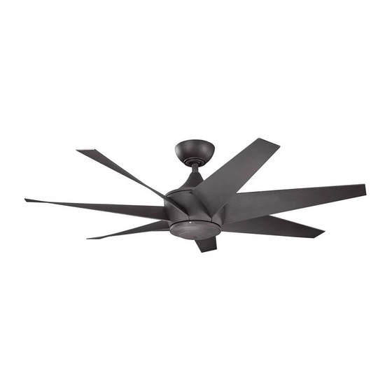
54" Lehr II
TM
A Kichler
®
Decor
™
ceiling fan
Advertisement
Table of Contents

Subscribe to Our Youtube Channel
Related Manuals for Kichler Lighting Lehr II


Summary of Contents for Kichler Lighting Lehr II
- Page 1 54” Lehr II A Kichler ® Decor ™ ceiling fan Includes our new CoolTouch 6 Speed DC Control System Looks permanent, but goes wherever you go! U.S. Patent Pending Kichler ® Lighting 7711 East Pleasant Valley Road P.O. Box 318010...
-
Page 2: Safety Rules
1. SAFETY RULES 1. To reduce the risk of electric shock, insure 8. WARNING: Use only with light kit marked electricity has been turned off at the circuit "Suitable for Use in Wet Locations". breaker or fuse box before beginning. 9. -
Page 3: Tools And Materials Required
54” Lehr 2. TOOLS AND MATERIALS REQUIRED Philips screw driver Blade screw driver 11 mm wrench Step ladder Wire cutters 3. PACKAGE CONTENTS Unpack your fan and check the contents. You should have the following items: Fan blade assembly (7) Canopy &... -
Page 4: Mounting Options
4. MOUNTING OPTIONS If there isn't an existing ETL listed mounting box, then read the following instructions. Disconnect the power by removing fuses or turning off circuit breakers. Secure the outlet box directly to the building structure. Use appropriate fasteners and Outlet box building materials. -
Page 5: Hanging The Fan
54” Lehr 5. HANGING THE FAN Hanger bracket REMEMBER to turn off the power before you begin. Ceiling To properly install your ceiling fan, follow the canopy steps below. Canopy cover Step 1. Remove the decorative canopy Fig. 5 bottom cover from the canopy by turning the cover counter clockwise. - Page 6 Step 8. Slip the coupling cover, canopy cover and canopy onto the downrod. Thread the hanger ball onto the downrod, insert the cross pin through the downrod and Downrod tighten. Now tighten the set screw. (Fig. 9) Canopy Step 9. Lift the motor assembly into position Canopy cover and place the hanger ball into the ceiling mounting bracket.
-
Page 7: Installation Of Safety Support
54” Lehr 6. INSTALLATION OF SAFETY SUPPORT (required for Canadian installation ONLY) A safety support cable is provided to help prevent the ceiling fan from falling, please Ceiling mounting install it as follows. Attach bracket safety cable Step 1. Attach the provided wood screw and to ceiling joist with screw and washers to the ceiling joist next to the... -
Page 8: Finishing The Installation
8. FINISHING THE INSTALLATION Step 1. Tuck all the connections neatly into the ceiling outlet box. Outlet box Step 2. Slide the canopy up to the mounting bracket and place one of the key hole slots Ceiling mounting over the mounting screw on the mounting bracket bracket. -
Page 9: Attaching The Fan Blades
54” Lehr 9. ATTACHING THE FAN BLADES Step 1 Attach the first blade assembly to the fan motor by lining up the slot of the blade assembly with the tab on the motor. Fasten the blade assembly to the motor using two screws and washer provided. -
Page 10: Installing The Mounting Plate
10. INSTALLING THE MOUNTING PLATE Step 1. Loosen the two screws on the mounting ring attached to the motor shaft and "remove" and save the third screw. (Fig. 16) Step 2. Place the key holes on the mounting plate over the 2 screws previously loosened from the mounting ring, turn mounting plate until it locks in place at the narrow section of the key holes. -
Page 11: Control System Set-Up
54” Lehr 12. CONTROL SYSTEM SET-UP Make sure the power is completely disconnected before you begin this procedure. SPECIAL NOTE: ® Your new Kichler Ceiling Fan is State of the Art and employs a High Efficiency DC (direct current) Motor with an advanced CoolTouch™ Remote Control System. - Page 12 2. Insert both batteries and make sure they Blue Light are seated correctly in each recess with the Positive + sign facing up. Replace the battery cover. (Figure 18) 3. Test the transmitter by pushing and releasing ANY button briefly. A Blue Light should illuminate under the 3-4 buttons.
- Page 13 54” Lehr 13. OPERATING INSTRUCTIONS: Speed Buttons Figure 22 1. Buttons 1, 2, 3, 4, 5 and 6 are used to set the blade speed as follows: 1 = Low Speed 2 = Medium Low Speed 3 = Medium Speed 4 = Medium High Speed 5 = High Speed 6 = Extra High Speed...
- Page 14 NOTE: Please remember your control system is an RF (Radio Frequency) control system. You may occasionally experience control problems because of other radio frequency interference, i.e. fan turns off, light turns off or won't turn on, speed changes, etc. If this should happen, just change the “Control Frequency”...
-
Page 15: Installing The Cooltouch Control System Wall Plate
54” Lehr ™ 14. INSTALLING THE COOLTOUCH Outlet box CONTROL SYSTEM WALL PLATE Switch Select a location to install your CoolTouch™ Wall plate Control System Transmitter. You can replace an existing wall switch or, install the transmitter on ANY flat surface. Option 1: Install the control system using an existing wall switch outlet box. -
Page 16: Troubleshooting
16. TROUBLESHOOTING Problem Solution Fan will not start. 1. Check circuit fuses or breakers. 2. Check all electrical connections to insure proper contact. CAUTION: Make sure the main power is OFF when checking any electrical connection. 3. Make sure the transmitter batteries are installed properly. Positive (+) side facing out.
Need help?
Do you have a question about the Lehr II and is the answer not in the manual?
Questions and answers