
Subscribe to Our Youtube Channel
Related Manuals for Kichler Lighting HATTERAS BAY PATIOLED 60"


Summary of Contents for Kichler Lighting HATTERAS BAY PATIOLED 60"
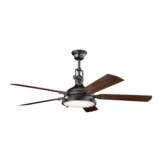
- Page 1 60" HATTERAS BAY PATIO LED Product images may vary slightly from actual product. INSTRUCTION MANUAL...
-
Page 3: Table Of Contents
TABLE OF CONTENTS SAFETY RULES............4 INSTALLING THE LIGHT PLATE AND GLASS LENS...16 TOOLS REQUIRED............ INSTALLING THE BATTERIES........17 PACKAGE CONTENTS ..........OPERATING INSTRUCTIONS ......... MOUNTING OPTIONS ..........INSTALLING THE TRANSMITTER........18 HANGING THE FAN ........... OPERATING INSTRUCTIONS ........INSTALLATION OF S AFETY SUPPORT....TROUBLESHOOTING............. -
Page 4: Safety Rules
SAFETY RULES To reduce the risk of electric shock, ensure electricity has been turned off at To avoid personal injury or damage to the fan and other items, be cautious when working around or cleaning the fan. the circuit breaker or fuse box before beginning. Do not use water or detergents when cleaning the fan or fan blades. -
Page 5: Tools Required
TOOLS REQUIRED PACKAGE CONTENTS Philips screw driver Unpack your fan and check the Blade screw driver contents. You should have the following items: 11 mm wrench Step ladder Wire cutters Fan blades (5) Ceiling mounting bracket c. Canopy d. Decorative mounting screw cover e. -
Page 6: Mounting Options
MOUNTING OPTIONS If there isn't an existing UL (cUL for Canadian Installation) listed mounting box, then read the following instructions. Disconnect the power by removing fuses or turning off circuit breakers. Secure the outlet box directly to the building structure. Use appropriate fasteners and building materials. -
Page 7: Hanging The Fan
HANGING THE FAN NOTE: This ceiling fan is supplied with two types of hanging CUL Listed assemblies; a downrod and canopy mounting system and a "close to outlet box ceiling" Canopy ONLY system. The "close-to- ceiling" installation is recommended in rooms with less than 8-foot ceilings or in areas where additional space is desired from the floor to the fan blades. - Page 8 STANDARD CEILING INSTALLATION Cross pin Hanger ball Supply wires Step 1. Remove the hanger ball from the downrod assembly by loosening the set screw, Set screw Downrod removing the cross pin and sliding the ball off the rod. (Fig. 6) Canopy Step 2.
- Page 9 STANDARD CEILING INSTALLATION (continued) Step 5. Lift the motor assembly into position and place the hanger ball Registration slot into the ceiling mounting bracket. Rotate the entire assembly until the "Check Tab" has dropped into the Check tab "Registration Slot" and seats firmly. (Fig. 7) The entire motor assembly should not rotate (left or right) when seated properly.
- Page 10 CLOSE-TO-CEILING Canopy INSTALLATION Decorative canopy Step 1. Remove the decorative canopy bottom bottom cover cover from the canopy. (Fig. 8) Fig. 8 Step 2. Remove three of the six screws and lock washers (every other one) from the coupler on top of the motor assembly.
-
Page 11: Installation Of Safety Support
INSTALLATION OF SAFETY SUPPORT (required for Canadian installation ONLY) A safety support cable is provided to help prevent the ceiling fan from falling, please install it as follows. Step 1. Attach the provided wood screw and washers to the ceiling joist Hanger bracket next to the mounting bracket but do not tighten. -
Page 12: Electrical Connections
ELECTRICAL CONNECTIONS Code switch WARNING: To avoid possible electrical shock, be sure you have turned off the power at the main circuit panel. ON ECE Follow the steps below to connect the fan to your household wiring. 1 1 2 Use the wire connecting nuts suppled with your fan. - Page 13 ELECTRICAL CONNECTIONS (continued) Outlet box Step 2. Motor to Receiver Electrical Connections: (Fig. 14) Connect White (neutral) Black (hot) the black wire from the fan to the black wire marked "TO MOTOR L" Green or bare on the receiver. Connect the white wire from the fan to the white wire copper (ground) Black ("AC IN L") marked "TO MOTOR N"...
-
Page 14: Finishing The Installation
FINISHING THE INSTALLATION Outlet box Ceiling mounting bracket STANDARD CEILING INSTALLATION Screws Step 1. Tuck all the connections neatly into the ceiling outlet box. Canopy Decorative mounting Step 2. Slide the canopy up to the ceiling and attach the canopy to the ceiling screw cover mounting bracket using 4 screws at the top edge of the mounting bracket. -
Page 15: Attaching The Fan Blades
ATTACHING THE FAN BLADES Step 1. Place a blade between a blade bracket and a blade bracket Screws medallion. Attach all three pieces using the screws , fiber washers and Blade Fiber washers iron washers provided. (Fig. 17) Iron washers bracket medallions Make sure the blade is straight when set on the blade bracket and the... -
Page 16: Installing The Light Plate And Glass Lens
INSTALLING THE LED LIGHT PLATE AND GLASS LENS Step 1. Loosen the three mounting screws on the inside of the light fixture and "remove" and save the fourth screw. (Fig.19) Step 2. Hold the light plate close to the light fixture and connect the white wires from the light plate and the fan. -
Page 17: Installing The Batteries
INSTALLING THE BATTERIES Remove the face plate of the Wall Switch by lifting at the top and then insert the supplied 12V battery. Duracell MN21/ Eveready A23/GP 23A all 12V. Replace the switch face plate. FAN OFF 1 2 3 4 To prevent possible damage to the transmitter, remove these batteries if not used for long periods of time (months). -
Page 18: Installing The Transmitter
Wall outlet box Wall switch INSTALLING THE TRANSMITTER Wall plate NOTE: All wiring and transmitter installation must be in accordance with the National Electrical Code and local electrical codes. Electrical installation should be performed by a qualified licensed electrician. WARNING: Shut off main power at the circuit breaker or fuse panel before continuing. -
Page 19: Operating Instructions
OPERATING INSTRUCTIONS NOTE: To operate the reverse function on this fan, press the reverse button while the fan is running. Warm weather - Forward (counter clockwise) A downward airflow creates a cooling effect as shown in Fig. 25. This allows you to set your air conditioner on a warmer setting without affecting your comfort. -
Page 20: Troubleshooting
TROUBLESHOOTING Problem Solution Fan will not start. 1. Check circuit fuses or breakers. 2. Check all electrical connections to ensure proper contact. CAUTION: Make sure the main power is OFF when checking any electrical connection. 3. Make sure transmitter batteries are installed properly, and ensure the batteries have a good charge. Fan sounds noisy. -
Page 21: Specifications
SPECIFICATIONS Fan Size Speed Volts Amps Watts CFM/W N.W. G.W. C.F. High 0.57 69.00 6665.26 60" Medium 0.52 41.40 4978.95 3.09' 0.35 16.80 2751.10 These are approximate measurements. They do not include data for any lamps or fixtures attached to the ceiling fan. FCC Information This device complies with part 15 of the FCC Rules. - Page 22 www.kichler.com KICHLER® LIGHTING 7711 EAST PLEASANT VALLEY ROAD CLEVELAND, OHIO 44131 CUSTOMER SERVICE 866.558.5706 8:00 AM TO 5:00 PM EST, MONDAY - FRIDAY...
- Page 23 VENTILATEUR À LED HATTERAS BAY PATIO 60 po Le produit peut différer légèrement des illustrations. MANUEL D’INSTRUCTIONS...
- Page 25 TABLE DES MATIÈRES RÈGLES DE SÉCURITÉ..........4 INSTALLATION DE LA PLAQUE LUMINEUSE ET LA LENTILLE EN VERRE..........16 OUTILLAGE REQUIS..........INSTALLATION DES PILES..........17 CONTENU DE L’EMBALLAGE........INSTRUCTIONS D'UTILISATION........OPTIONS DE MONTAGE..........INSTALLATION DU TRANSMETTEUR ......18 SUSPENDRE LE FAN..........INSTRUCTIONS D'UTILISATION ........INSTALLATION DU SUPPORT DE SÉCURITÉ..
-
Page 26: Règles De Sécurité
RÈGLES DE SÉCURITÉ Pour réduire le risque d’électrocution, assurez-vous que l’électricité a été Éviter de placer des objets dans la trajectoire des pales. coupée au niveau du disjoncteur ou de la boîte à fusibles avant de Pour éviter des blessures ou des dommages au ventilateur et autres objets, prendre commencer. -
Page 27: Outillage Requis
CONTENU DE L’EMBALLAGE OUTILLAGE REQUIS Déballez votre ventilateur et vérifiez le contenu. Vous devriez avoir à votre Tournevis Philips disposition les éléments suivants : Tournevis standard Pale Clé de 11 mm Pales de ventilateur (5) Escabeau b. Support de montage au plafond Coupe-fil c. -
Page 28: Options De Montage
OPTIONS DE MONTAGE En l'absence d'une boîte de montage homologuée cUL (UL pour les États-Unis), prendre connaissance des instructions suivantes. Débrancher l'alimentation en retirant les fusibles ou en déclenchant les disjoncteurs de la boîte à prises. Fixer la boîte à prises directement sur la structure du bâtiment. Boîte à... -
Page 29: Suspendre Le Fan
SUSPENDRE LE FAN REMARQUE: Ce ventilateur de plafond est fourni avec deux types Boîte de sortie d'assemblages suspendus; un système de montage de tige et de verrière répertoriée et un système SEULEMENT "au plafond près du plafond". L'installation "au plafond" est recom-mandée dans les pièces avec des plafonds de moins de 8 pieds ou dans les zones où... - Page 30 INSTALLATION STANDARD AU PLAFOND Broche croisée Boule de suspension Fils d'alimentation Étape 1. Retirez la boule de suspension de l’assemblage de la tige descendante en desserrant Vis de réglage Tige de la vis de réglage, en retirant la goupille transversale et en faisant glisser la boule de la tige. suspension (Fig.6) Canopée...
- Page 31 INSTALLATION STANDARD AU PLAFOND (suite) Étape 5. Soulevez l'ensemble du moteur en position et placez la boule Fente d'inscription de suspension dans le support de fixation au plafond. Onglet Vérifier Faites pivoter l’ensemble complet jusqu’à ce que le "Check Tab" soit tombé...
- Page 32 INSTALLATION Canopée PROCHE PLAFOND Couvercle inférieur à Étape 1. Retirez le couvercle inférieur du dais baldaquin décoratif décoratif du dais. (Fig. 8) Fig. 8 Étape 2. Retirez trois des six vis et rondelles de blocage (toutes les deux) du coupleur situé au- dessus de l'ensemble moteur.
-
Page 33: Installation Du Support De Sécurité
INSTALLATION DU SUPPORT DE SÉCURITÉ (requis UNIQUEMENT dans le cas d'une installation canadienne) Un câble de support de sécurité est fourni pour empêcher que le ventilateur de plafond ne tombe. Veuillez l’installer comme suit. Étape 1. Fixez la vis à bois et les rondelles fournies à la solive du Crochet de suspension plafond à... -
Page 34: Connexions Électriques
CONNEXIONS ÉLECTRIQUES Commutateur de code AVERTISSEMENT : Pour éviter tout risque d'électrocution, s'assurer que l'alimentation est coupée au niveau du panneau de circuit principal. ON ECE 1 1 1 2 Procédez comme suit pour raccorder le ventilateur au câblage du FAN OFF domicile. - Page 35 CONNEXIONS ÉLECTRIQUES Boîte à prises (suite) Blanc (neutre) Noir (sous tension) Étape 2. Connexions électriques entre le moteur et le récepteur : (Fig. 14) Vert ou cuivre nu (terre) Connectez le fil NOIR du ventilateur au fil noir marqué "TO MOTOR L" du Noir («AC IN L») récepteur.
-
Page 36: Finition De L'installation
FINITION DE L'INSTALLATION Boîte de sortie Support de montage au plafond INSTALLATION DE PLAFOND STANTARD Des vis Canopée Couvercle de vis de Étape 1. Rentrez soigneusement toutes les connexions dans la boîte de sortie du montage plafond. décoratif Couverture de la canopée Étape 2. -
Page 37: Fixation Des Pales De Ventilateur
FIXATION DES PALES DE VENTILATEUR Des vis Rondelles de fibres Étape 1. Placez une lame entre un support de lame et un médaillon de Rondelles de fer Support de lame support de lame. Fixez les trois pièces à l’aide des vis, des rondelles en fibre et des rondelles en fer fournies. -
Page 38: Installation De La Plaque Lumineuse Et La Lentille En Verre
INSTALLATION DE LA PLAQUE LUMINEUSE ET LA LENTILLE EN VERRE Étape 1. Desserrez les trois vis de montage à l'intérieur du luminaire et "retirez" et conservez la quatrième vis. (Fig. 19) Étape 2. Tenez la plaque d'éclairage près du luminaire et connectez les Luminaire fils blancs de la plaque d'éclairage et du ventilateur. -
Page 39: Installation Des Piles
INSTALLATION DES PILES Retirez la plaque avant de l'interrupteur mural en la soulevant par le haut et placez ensuite la pile 12 V (fournie). Duracell MN21/ Eveready A23/GP 23A toutes de 12 V. Replacez la plaque avant de l'interrupteur. FAN OFF 1 2 3 4 Pour éviter d'endommager l'émetteur, retirez ces piles s'il ne sera pas utilisé... -
Page 40: Installation Du Transmetteur
Boîtier électrique au mur Interrupteur mural INSTALLATION DU TRANSMETTEUR Plaque murale REMARQUE : La totalité du câblage et de l’installation du transmetteur doit être complétée conformément au code électrique national et aux codes électriques locaux. L’installation électrique devrait être réalisée par un électricien qualifié détenteur d’une licence. AVERTISSEMENT : Fermer l’alimentation électrique au panneau principal de disjoncteurs ou de fusibles avant de poursuivre. -
Page 41: Instructions D'utilisation
INSTRUCTIONS D'UTILISATION REMARQUE: Pour utiliser la fonction d'inversion sur ce ventilateur, appuyez sur le bouton d'inversion pendant le fonctionnement du ventilateur. Temps chaud - Avant (sens antihoraire) Un flux d'air vers le bas crée un effet de refroidissement (voir la figure 25). Ceci vous permet de régler votre climatisation pour une température plus élevée sans affecter votre confort. -
Page 42: Dépannage
DÉPANNAGE Problème Solution Impossible de mettre le 1. Vérifiez les fusibles ou disjoncteurs de circuit. ventilateur en marche. 2. Vérifiez tous les raccordements électriques pour garantit un bon contact. MISE EN GARDE : Assurez-vous que l'alimentation principale est COUPÉE lors de la vérification des raccordements électriques. 3. -
Page 43: Caractéristiques
CARACTÉRISTIQUES Taille Vitesse Volts Amplis Watts CFM/W N.W. G.W. C.F. Haute 0.57 69.00 6665.26 60" Moyen 0.52 41.40 4978.95 3.09' Faible 0.35 16.80 2751.10 Ce sont des mesures approximatives. Ils ne comprennent pas les données pour les lampes ou les luminaires fixés au ventilateur de plafond. FCC Information Cet appareil est conforme à... - Page 44 www.kichler.com KICHLER® LIGHTING 7711 EAST PLEASANT VALLEY ROAD CLEVELAND, OHIO CLEVELAND, OHIO 44131 SERVICE À LA CLIENTÈLE 866.558.5706 De 08h à 17h (heure normale du l'Est), du lundi au vendredi...
- Page 45 VENTILADOR CON LED DE 60" HATTERAS BAY PATIO Las imágenes del producto pueden variar levemente respecto del producto real. MANUAL DE INSTRUCCIONES...
- Page 47 ÍNDICE NORMAS DE SEGURIDAD..........4 INSTALANDO LA PLACA DE LUZ Y LA LENTE DE CRISTAL..........16 HERRAMIENTAS REQUERIDAS........INSTALANDO LAS BATERÍAS........17 CONTENIDO DEL ENVASE ..........INSTRUCCIONES DE OPERACIÓN ........ OPCIONES DE MONTAJE ..........INSTALACIÓN DEL TRANSMISOR....... 18 COLGANDO EL VENTILADOR ........INSTRUCCIONES DE OPERACIÓN ......
-
Page 48: Normas De Seguridad
NORMAS DE SEGURIDAD Para reducir el riesgo de sufrir una descarga eléctrica, asegúrese de Para evitar lesiones o daños al ventilador u otros objetos, sea cuidadoso al trabajar cerca del ventilador o limpiarlo. deshabilitar el circuito o cortar la electricidad de la caja de fusibles antes de comenzar. -
Page 49: Herramientas Requeridas
HERRAMIENTAS REQUERIDAS CONTENIDO DEL ENVASE Retire el ventilador de la caja y verifique que Destornillador Philips estén todos sus componentes. La caja Destornillador plano debería contener los siguientes elementos: Llave de 11 mm Escalera Aspas del ventilador (5) Cortacables Soporte de montaje en el techo Pabellón Tapa decorativa de tornillo de montaje... -
Page 50: Opciones De Montaje
OPCIONES DE MONTAJE Si no hay ninguna caja de montaje existente con certificación UL (cUL para instalación en Canadá), entonces lea las siguientes instrucciones. Desconecte el suministro de energía eléctrica retirando los fusibles o apagando los disyuntores. Sujete la caja de distribución directamente a la estructura de la Caja de distribución construcción. -
Page 51: Colgando El Ventilador
COLGANDO EL VENTILADOR NOTA: Este ventilador de techo se suministra con dos tipos de Caja de salide conjuntos colgantes; un sistema de montaje de techo y techo y un listada por sistema SOLO de dosel "cerca del techo". Se recomienda la instalación "cerca del techo"... - Page 52 INSTALACIÓN ESTÁNDAR DE TECHO Pasador de cruz Bola de suspensión Cables de suministro Paso 1. Retire la bola de suspensión del conjunto de la varilla aflojando aflojando el tornillo Tornillo de ajuste Varilla de fijación, retirando el pasador transversal y deslizando la bola fuera de la varilla. (Fig.6) Pabellón Paso 2.
- Page 53 INSTALACIÓN ESTÁNDAR DE TECHO (continuación) Paso 5. Levante el conjunto del motor a su posición y coloque la bola Espacio de registro de suspensión en el soporte de montaje en el techo. Pestaña de verificación Gire todo el conjunto hasta que la "pestaña de verificación" haya caído en la "ranura de registro"...
- Page 54 INSTALACIÓN CERCA Pabellón DEL TECHO Cubierta inferior Paso 1. Retire la cubierta inferior del dosel decorativa decorativo del dosel. (Fig. 8) del dosel Fig. 8 Paso 2. Retire tres de los seis tornillos y arandelas de seguridad (cada uno) del acoplador en la parte superior del conjunto del motor.
-
Page 55: Instalación Del Soporte De Seguridad
INSTALACIÓN DEL SOPORTE DE SEGURIDAD (SE REQUIERE ÚNICAMENTE PARA SU INSTALACIÓN EN CANADÁ) Se incluye un cable de soporte de seguridad que contribuye a evitar que el ventilador de techo se caiga, instálelo de la siguiente manera. Paso 1. Inserte el tirafondo y arandelas proporcionados en el colgante Soporte de suspensión de viga junto al soporte de montaje, pero no ajuste. -
Page 56: Conexiones Eléctricas
CONEXIONES ELÉCTRICAS Interruptor de códigos ADVERTENCIA: Para evitar una posible descarga eléctrica, asegúrese de haber apagado la alimentación en el panel del circuito principal. ON ECE Siga los pasos a continuación para conectar el ventilador al cableado 1 1 2 de su hogar. - Page 57 CONEXIONES ELÉCTRICAS Caja de (continuación) distribución Paso 2. Conexiones eléctricas del motor al receptor: (Fig. 14) Blanco (neutro) Negro (caliente) Conecte el cable negro del ventilador al cable negro marcado como Verde o cobre sin "TO MOTOR L” (AL MOTOR L) del receptor. Conecte el cable blanco recubrimiento (a tierra) Negro (“CA EN L”) del ventilador al cable blanco marcado como "TO MOTOR N”...
-
Page 58: Acabado De La Instalación
ACABADO DE LA INSTALACIÓN Caja de salida Soporte de montaje en INSTALACIÓN DE TECHO ESTÁNDAR el techo Empulgueras Paso 1. Meta todas las conexiones perfectamente en la caja de salida del techo. Pabellón Tapa Paso 2. Deslice el dosel hacia el techo y fije el dosel al soporte de montaje del techo con decorativa de tornillo 4 tornillos en el borde superior del soporte de montaje. -
Page 59: Colocación De Las Hojas Del Ventilador
COLOCACIÓN DE LAS HOJAS DEL VENTILADOR Empulgueras Medallones Arandelas de fibra de soporte Paso 1. Coloque una cuchilla entre un soporte de cuchilla y un Arandelas de hierro de cuchilla medallón de soporte de cuchilla. Fije las tres piezas con los tornillos, arandelas de fibra y arandelas de hierro provistas. -
Page 60: Instalando La Placa De Luz Yla Lente De Cristal
INSTALANDO LA PLACA DE LUZ Y LA LENTE DE CRISTAL Paso 1. Afloje los tres tornillos de montaje en el interior de la lámpara y "quite" y guarde el cuarto tornillo. (Fig. 19) Paso 2. Mantenga la placa de luz cerca de la lámpara y conecte los cables blancos de la placa de luz y el ventilador. -
Page 61: Instalando Las Baterías
INSTALANDO LAS BATERÍAS Retire la placa frontal del interruptor de pared levantando la parte superior y luego inserte la batería de 12V suministrada. Duracell MN21 / Eveready A23 / GP 23A todos 12V. Vuelva a colocar la placa frontal del interruptor. FAN OFF 1 2 3 4 Para evitar posibles daños al transmisor, retire estas baterías si no las... -
Page 62: Instalación Del Transmisor
Caja de conexión Interruptor de pared INSTALACIÓN DEL TRANSMISOR Placa de pared NOTA: Todo el cableado y la instalación del transmisor deben estar de acuerdo con el Código Nacional de Electricidad y los códigos de electricidad locales. La instalación eléctrica debe ser realizada por un electricista cualificado y autorizado. -
Page 63: Instrucciones De Operación
INSTRUCCIONES DE OPERACIÓN NOTA: Para operar la función de retroceso en este ventilador, presione el botón de retroceso mientras el ventilador está funcionando. Clima cálido: hacia adelante (en sentido antihorario) Un flujo de aire hacia abajo crea un efecto de enfriamiento como se muestra en la Fig. 25. Esto le permite configurar su aire acondicionado en un ambiente más cálido sin afectar su comodidad. -
Page 64: Localización Y Resolución De Problemas
LOCALIZACIÓN Y RESOLUCIÓN DE PROBLEMAS Problema Solución El ventilador no arranca. 1. Controle el funcionamiento de los fusibles de circuito o los disyuntores. 2. Verifique todas las conexiones eléctricas para asegurar el debido contacto. PRECAUCIÓN: Asegúrese de que la corriente principal esté DESCONECTADA al verificar cualquier conexión eléctrica. Asegúrese de que las baterías del transmisor estén instaladas correctamente, y que las baterías estén bien cargadas. -
Page 65: Especificaciones
ESPECIFICACIONES Tamaño Velocidad Voltios Amps Vatios CFM/W N.W. G.W. C.F. Alto 0.57 69.00 6665.26 60" Medio 0.52 41.40 4978.95 3.09' Bajo 0.35 16.80 2751.10 Estas son medidas aproximadas. No incluyen datos de ninguna lámpara o accesorio conectado al ventilador de techo. Información de la FCC: Este dispositivo cumple con la parte 15 de las Reglas de la FCC. - Page 66 www.kichler.com KICHLER® LIGHTING 7711 EAST PLEASANT VALLEY ROAD CLEVELAND, OHIO 44131 SERVICIO DE ATENCIÓN AL CLIENTE 866.558.5706 8:00 AM A 5:00 PM HORA DEL ESTE, DE LUNES A VIERNES...
Need help?
Do you have a question about the HATTERAS BAY PATIOLED 60" and is the answer not in the manual?
Questions and answers