Table of Contents
Advertisement
Quick Links
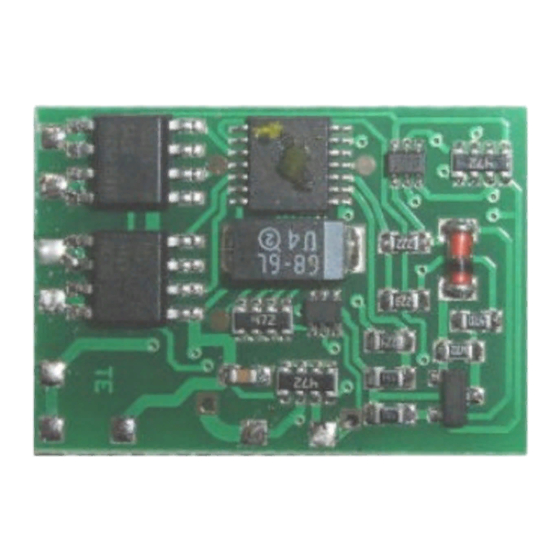
Lastgeregelter Lokdecoder
für Gleichstrommotoren
DC engines - DCC format
Décodeur avec compensation de
charge pour locomotive avec
moteur continu - Format DCC
Lastgeregelde Locdecoder
voor gelijkstroommotoren
LD-G-24
DCC-Format
Locomotive Decoder
with load control for
DCC-format
Art.-Nr. 22-01-086
Art.-Nr. 22-01-087
n
n
n
n
n
n
n
n
n
Anleitung
n
Manual
n
Mode d´emploi
n
Handleiding
n
n
n
n
Advertisement
Table of Contents

Related Manuals for tams elektronik LD-G-24


Summary of Contents for tams elektronik LD-G-24
- Page 1 LD-G-24 Lastgeregelter Lokdecoder für Gleichstrommotoren DCC-Format Locomotive Decoder with load control for Anleitung DC engines - DCC format Décodeur avec compensation de Manual charge pour locomotive avec Mode d´emploi moteur continu - Format DCC Lastgeregelde Locdecoder Handleiding voor gelijkstroommotoren DCC-format Art.-Nr.
- Page 2 © 01/2007 Tams Elektronik GmbH Alle Rechte, insbesondere das Recht der Vervielfältigung und Verbreitung sowie der Übersetzung vorbehalten. Vervielfältigungen und Reproduktionen jeglicher Form bedürfen schriftlichen Genehmigung durch die Tams Elektronik GmbH. Deutsch Technische Änderungen vorbehalten. English © 01/2007 Tams Elektronik GmbH All rights reserved.
-
Page 3: Table Of Contents
LD-G-24 English Table of contents How to use this manual Intended use Safety instructions EMC declaration Operation overview Technical specifications Checking the package contents Required tools and materials Safe and correct soldering Mounting the locomotive decoder Programming the locomotive decoder... -
Page 4: How To Use This Manual
English LD-G-24 How to use this manual Even if you have no specialist technical training, this manual gives step- by-step instructions for safe and correct fitting of the module, and operation. Before you start, we advise you to read the whole manual, particularly the chapter on safety instructions and the FAQ chapter. -
Page 5: Safety Instructions
LD-G-24 English Safety instructions Mechanical hazards Cut wires can have sharp ends and can cause serious injuries. Watch out for sharp edges when you pick up the PCB. Visibly damaged parts can cause unpredictable danger. Do not use damaged parts: recycle and replace them with new ones. - Page 6 English LD-G-24 Fire risk Touching flammable material with a hot soldering iron can cause fire, which can result in injury or death through burns or suffocation. Connect your soldering iron or soldering station only when actually needed. Always keep the soldering iron away from inflammable materials.
-
Page 7: Emc Declaration
LD-G-24 English EMC declaration This product is developed in accordance with the European standards EN 55014 and EN 50082-1, tested corresponding to the EC - directive 89/336/EWG (EMVG of 09/11/1992, electromagnetic tolerance) and meets legal requirements. To guarantee the electromagnetic tolerance you must take the following precautions: §... -
Page 8: Operation Overview
LD-G-24 Operation overview The decoder LD-G-24 is designed for operation in DCC format and can be adjusted to one of 127 basic addresses or to one of 10.239 extended addresses. It is designed to be controlled from digital control units that are set on the 14-, 28- or the 128-speed mode. - Page 9 LD-G-24 English § Maximum voltage (CV#5) * § Version (CV#7) – read only § Manufacturer identification (CV#8) - read only § Extended address (CV#17 and CV#18) * § Configuration data 1 (CV#29) § Assignment of the outputs X4 to X7 to the function keys F5 to F8 (CV#39 to 42) * §...
- Page 10 English LD-G-24 Attention: For most locomotives you will achieve good driving characteristics with the factory settings. Incorrect of the load control parameter settings deteriorate the driving characteristics of the motor considerably. Therefore you should first check the locomotive with the preset values and modify the parameters of the load control only step-by-step.
- Page 11 LD-G-24 English Shunting gear In the speed modes 14 and 28, it is possible to switch into the shunting gear mode via a function key, when so programmed. In the shunting gear mode, the velocity of all speed levels is reduced to approx. 50 % compared to the set velocity.
-
Page 12: Technical Specifications
English LD-G-24 § Switching on and off depending on the direction of travel. § Flashing with a frequency of 2 Hz with two phases which are out- of-phase by 180 degrees. Example of use: individual flash lights or alternating flash lights. -
Page 13: Required Tools And Materials
LD-G-24 English Required tools and materials Make sure you have the following tools, equipment and materials ready for use: § an electronic soldering iron (max. 30 Watt) with a fine tip, § a soldering iron stand, § a tip-cleaning sponge, §... -
Page 14: Mounting The Locomotive Decoder
English LD-G-24 § Apply the soldering tip to the soldering spot in such a way that the wire and the soldering eye are heated at the same time. Simultaneously add solder (not too much). As soon as the solder becomes liquid take it away. - Page 15 LD-G-24 English Solder the connections from the rail current collectors at the points X1 and X2. Next solder the connections from the motor at the points X11 and X12. In case the locomotive´s direction of motion in analogue mode does not match the direction of motion set at the speed control you have to swap the connections to the points X11 and X12.
- Page 16 English LD-G-24 Caution: The return conductor for all functions (point X3) must under no circumstances be connected to locomotive ground. Possible short circuit! The locomotive decoder will be damaged in operation. Tip: Before starting to program the locomotive decoder you should connect the motor to the decoder.
- Page 17 LD-G-24 English of 7 x 19 mm. Fix the heat sink on the diodes D1 to D4, using an appropriate glue ( e.g. super glue ). Take care that the heat sink does not contact the adjoining IC1. Risk of short circuit!
-
Page 18: Programming The Locomotive Decoder
English LD-G-24 Programming the locomotive decoder The locomotive decoder is programmed from the digtial central. See the chapter in the manual of your digital control unit where the programming of configuration variables (CVs) is explained. You can programm resp. read out the following locomotive decoder variables: NB. - Page 19 LD-G-24 English CV-name Remarks Input value / (State of delivery) Maximum 0 ... 255 = The voltage to be output to voltage the motor at the highest speed level. The value "2" corresponds to 0,8 %, the value "255" to 100 % of the max.
- Page 20 English LD-G-24 CV-name Remarks Input value / (State of delivery) Assignment 0 ... 15 Numerical value * F5 – F8 to Operation with: the outputs: function key F5 function key F6 function key F7 function key F8 Configuration 0 ... 127...
- Page 21 LD-G-24 English CV-name Remarks Input value / (State of delivery) Assignment 0 ... 31 Numerical value * F0 – F4 to Operation with: the outputs: (16) function key F1 (16) function key F2 function key F3 function key F4 function key F0 Parameter of 0 ...
-
Page 22: Improvement Of The Driving Characteristics
English LD-G-24 Improvement of the driving characteristics Locomotives with especially high current consumption or track sections with bad contacts (e.g. some types of points) may give an unsatisfactory performance. improve locomotive performance by soldering a capacitor 100 µF / 35 V between X8 and X15 (see fig. -
Page 23: Manufacturer's Note
LD-G-24 English § After programming the decoder the locomotive does not run or runs badly. Possible cause: The set values for the CV are inconsistent. à Perform a decoder reset and program the decoder anew. § In digital mode the locomotive suddenly runs very fast. -
Page 24: Conditional Warranty
English LD-G-24 Conditions of warranty This product is guaranteed for two years. The warranty includes the correction of faults which can be proved to be due to material failure or factory flaw. guarantee adherence technical specifications of the circuit when assembled and connected according to the manual. - Page 25 LD-G-24 LD-G-24 Fig. 1: Fig. 2: Anschluß LD-G-24 / Connections LD-G-24 Anschluß LD-G-24 / Connections LD-G-24 Connexion LD-G-24 / Aansluiten LD-G-24 Connexion LD-G-24 / Aansluiten LD-G-24 Schienenabnehmer links / Rail current collectors left Prises de courant de la voie gauches / Railstroomafnemers links...
- Page 26 LD-G-24 LD-G-24 Fig. 4: Schaltplan - Circuit diagram - Schéma de principe - Schakelschema Seite - Page - Page - Pagina II Seite - Page - Page - Pagina II...
- Page 27 Actuele informatie en tips: http://www.tams-online.de Garantie und Service: Warranty and service: Garantie et service: Garantie en service: Tams Elektronik GmbH Rupsteinstraße 10 D-30625 Hannover fon: +49 (0)511 / 55 60 60 fax: +49 (0)511 / 55 61 61 e-mail: info@tams-online.de...
Need help?
Do you have a question about the LD-G-24 and is the answer not in the manual?
Questions and answers