Table of Contents
Advertisement
Quick Links
Advertisement
Table of Contents

Subscribe to Our Youtube Channel
Related Manuals for Kartsana TGE-241 Series


Summary of Contents for Kartsana TGE-241 Series
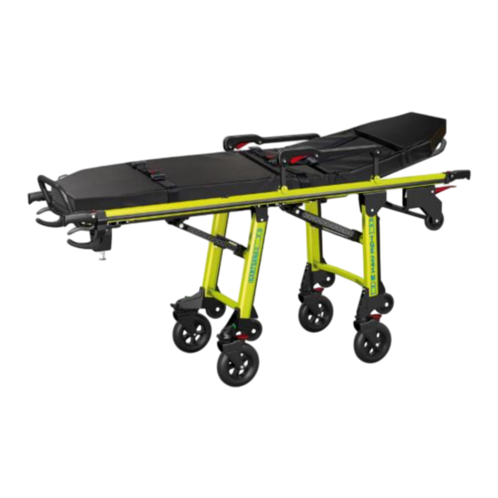
- Page 1 C/ Narcís Monturiol, 34 08192 Sant Quirze del Vallès BARCELONA TEL. 93 714-49-24 ventas@kartsana.com www.kartsana.com INSTRUCTIONS MANUAL SERIE TGE-241 COMPACT STRETCHER Models TGE-241-M, TGE-241-XL Please read the instruction manual before usage and keep them for future reference.
-
Page 3: Table Of Contents
OPERATION AND HANDLING OF THE TGE-241 SERIES CONTENTS 1.- INTRODUCTION 1.1.- F OREWORD 1.2.- R ESPONSIBILITY AND WARRANTY 1.3.- S PECIFICATIONS 1.4.- A TTENTION 1.5.- S UMMARY OF SAFETY PRECAUTIONS 2.- INSTRUCTIONS MANUAL 2.1.- T ECHNICAL SPECIFICATIONS 2.1.1.- T TGE-241-M / XL ECHNICAL SPECIFICATIONS 2.2.- O... - Page 4 OPERATION AND HANDLING OF THE TGE-241 SERIES Rev.4 20-12-17...
-
Page 5: Introduction
1.1.- Foreword TGE-241 series is specially designed for the rescue and transportations of patients. TGE-241 series is and has been tested in accordance with the UNE-EN 1865 and UNE-EN 1789 standards. All the information regarding treatment, disinfection and maintenance is indicated, taking into consideration our current experience and know-how. -
Page 6: Attention
- High obstacles such as curbing, steps or rough terrain can cause the stretcher to tip, possibly causing injury to the patient or operator. - TGE-241 series is designed to be compatible with Kartsana models R-419 / R-450 -S / R-800 and R-900, and is operator responsibility that these products work together. - Page 7 - Kartsana recommends that, prior to installation, the certified mechanic plan the placement of the safety hook in the rear of the vehicle.
-
Page 8: Instructions Manual
OPERATION AND HANDLING OF THE TGE-241 SERIES 2.- INSTRUCTIONS MANUAL TGE-241 series is adapted for mounting on Kartsana rails R-419, R-450-S inox, R-800 and R-900 To reduce the risk of injuries to the patient and accompanying persons in the event of an accident, it is advisable to avoid sharp edges and projecting parts inside the ambulance, paying special attention to the areas nearest to the stretcher. -
Page 9: Operating And Handling The Stretcher
OPERATION AND HANDLING OF THE TGE-241 SERIES 2.2.- Operating and handling the stretcher To prevent injuries to limbs and other body parts, make sure they are not within the range of the moving parts of the stretcher. Clarification: The front part of the stretcher corresponds to the head part. -
Page 10: Safety Rail
OPERATION AND HANDLING OF THE TGE-241 SERIES 2.2.3.- Safety rail The safety rail has a red bar that locks the rail into place. To lower the rail, just press the bar as shown in the figure below. To lock it in the safety position again, move it to that position manually, and it will automatically lock into place. - Page 11 OPERATION AND HANDLING OF THE TGE-241 SERIES With the “A” knob we can loosen and tighten the assembly where and when it is convenient. Unscrewing the knob “B” we remove the IV drip stand to the vertical position perpendicular to the stretcher, then we twist the knob again.
-
Page 12: Method For Fastening The Safety Belts On The Patient
OPERATION AND HANDLING OF THE TGE-241 SERIES 2.2.5.- Method for fastening the safety belts on the patient’s head and feet Place the clasps (C) in the position shown in the figure above. Pass the male part of the buckle (D) between the openings (C) until it is inserted into the female part B. -
Page 13: Dismantling-Assembling The Stretcher Safety Belts
OPERATION AND HANDLING OF THE TGE-241 SERIES 2.2.7.- Dismantling-assembling the stretcher safety belts Anchoring with a knot To dismantle the belts, pass the belt through the slot in the buckle as shown in the following figure. To assembly it, just follow the same process but in reverse order. - Page 14 OPERATION AND HANDLING OF THE TGE-241 SERIES 2.2.7.1.- Position of the belts 2.2.7.1.1.- Lateral belts The belts are positioned at the approximate distances shown in the figure below: 2.2.7.1.2.- Head belts The belts must be passed through the holes in the head rest part and secured on the crosspiece of the panel with a knot.
-
Page 15: Control For Operating The Stretcher Legs
OPERATION AND HANDLING OF THE TGE-241 SERIES 2.2.8.- Control for operating the stretcher legs 2.2.8.1.-Rear controls · Blue (right): Folds/unfolds the front leg of the stretcher. Blue lever · Orange (left) Folds/unfolds or activates the intermediate position of the rear leg of the stretcher. -
Page 16: Intermediate Positions Of The Stretcher
OPERATION AND HANDLING OF THE TGE-241 SERIES 2.2.8.2.- Lever front leg control It activates the intermediate positions of the front leg of the stretcher (the starting point is the unfolded position). Note: To return the leg to its original unfolded position, activate the front control and then raise that part of the stretcher manually so that the leg returns automatically. - Page 17 OPERATION AND HANDLING OF THE TGE-241 SERIES 1st Intermediate position: Hold the stretcher firmly with both hands to prevent it from making dangerous movements. Then the stretcher can also be inclined on one part (front or rear) by activating the controls as described above.
- Page 18 OPERATION AND HANDLING OF THE TGE-241 SERIES Tredelenburg position To perform this manoeuvre, activate the brakes on the front wheels and place them in the position shown on the adhesive, before activating the red lever at the side. It is achieved by activating the intermediate position lever (red) located on the right- hand side of the stretcher.
-
Page 19: Brake Lever
OPERATION AND HANDLING OF THE TGE-241 SERIES 2.2.10.- Brake lever Activate the red lever with your foot to enable the brake to lock the rear wheels. That special brake blocks both the longitudinal and the rotating movement of the stretcher. -
Page 20: Mounting The Stretcher On The Ambulance Stretcher Holder
In the event of not using the Kartsana rails, it is advisable that the front part of the stretcher cart be anchored at the end of the bar marked 12 in the exploded diagram... -
Page 21: Desinfection
OPERATION AND HANDLING OF THE TGE-241 SERIES 3.- DESINFECTION When disinfecting the stretcher, use products that will not damage the surface of the materials and wipe with a cloth or something similar. If the surface to be disinfected is greased, regreased it after disinfecting it. -
Page 22: Exploded Views
OPERATION AND HANDLING OF THE TGE-241 SERIES 5.- EXPLODED VIEWS 5.1.- TGE-241-M Rev.4 20-12-17... - Page 23 OPERATION AND HANDLING OF THE TGE-241 SERIES Rev.4 20-12-17...
- Page 24 OPERATION AND HANDLING OF THE TGE-241 SERIES 14-0310-001 ETIQUETA PESO MAX. 250 Kg. SERIE 241 Rev.4 20-12-17...
-
Page 25: Tge-241-Xl
OPERATION AND HANDLING OF THE TGE-241 SERIES 5.2.- TGE-241-XL Rev.4 20-12-17... - Page 26 OPERATION AND HANDLING OF THE TGE-241 SERIES Rev.4 20-12-17...
- Page 27 OPERATION AND HANDLING OF THE TGE-241 SERIES ETIQUETA PESO MAX. 250 Kg. SERIE 241 14-0310-001 The pieces that his number reference starts in 13-xxxx-xxx will be elements of fixation. The pieces that his number reference starts in 50-xxxx-xxx will be welding sets and it will be supplied like an inseparable set, not at loose parts.
- Page 28 OPERATION AND HANDLING OF THE TGE-241 SERIES Sistema de gestión certificado Rev.4 20-12-17...
Need help?
Do you have a question about the TGE-241 Series and is the answer not in the manual?
Questions and answers