Table of Contents
Advertisement
Quick Links
Advertisement
Table of Contents

Subscribe to Our Youtube Channel
Related Manuals for Kartsana BRAVA


Summary of Contents for Kartsana BRAVA
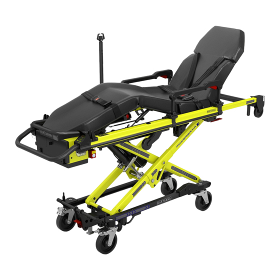
- Page 1 Pol. Ind. Can Carner. c/ Urgell, 1 08211 Castellar del Valles BARCELONA TEL. 93 714-49-24 Ventas@kartsana.com www.kartsana@kartsana.com INSTRUCTIONS MANUAL BRAVA POWER STRETCHER Read these maintenance instructions Before using the product and keep them For future reference. V1.0...
- Page 2 OPERATING AND HANDLING THE BRAVA POWER STRETCHER...
-
Page 3: Table Of Contents
2.2.10.1.- Side belts……………………………………………………………………………………..2.2.10.2.- Back rest belts …………………………………………………………………………..2.2.11.- Back wheel brake lever ……………………………………………………………………………….. 17 2.2.12.- Back wheel release lever ……….…………………………………………………………………….. 17 2.2.13.- Joining the brava stretcher to the bravo rail ………………………………………………………… 18 3.- Faults ………..............................21 4.- Disinfection……………………........................5.- Maintenance…………………........................ -
Page 4: Foreword
Manual operation is possible when potential faults in the automated system occur. The BRAVA stretcher model must be joined to the ambulance using the KARTSANA BRAVO rail. -
Page 5: Warranty And Liability
Kartsana or its respective representative. The manufacturer will not be liable for any anomaly caused to the stretcher as a result of using products other than those provided by Kartsana. Other warranty clauses, see the Warranty Terms and Conditions that are supplied with the product. -
Page 6: Instructions Manual
OPERATING AND HANDLING THE BRAVA POWER STRETCHER 2.- INSTRUCTIONS MANUAL 2.1.- Technical specifications BRAVA stretcher Make sure that no damage is caused to the areas containing the stretcher mechanisms, to prevent them from malfunctioning. Stretcher weight 69 kg Trolley dimensions: Elevation in mm... -
Page 7: Operating And Using The Brava Stretcher
2.2.- Operating and handling the stretcher 2.2.1.-Installing the battery The first step when working with Brava is to install the two 24 V. batteries which power the system. To do this, we open the rear black cover and place the batteries opposite their housings at the back of the stretcher and push until it locks. -
Page 8: Starting And Controlling The Stretcher
OPERATING AND HANDLING THE BRAVA POWER STRETCHER 2.2.2.-Starting and controlling the stretcher. To avoid potential injury to the patient and companions, do not place objects in the way of the moveable parts of the stretcher. It is also recommended to avoid having objects that stick out the ambulance. -
Page 9: Incidents Display Panel
OPERATING AND HANDLING THE BRAVA POWER STRETCHER shows that they are half charged and if they show red we are being warned that we must recharge the batteries as they may soon stop working due to the low voltage level. - Page 10 OPERATING AND HANDLING THE BRAVA POWER STRETCHER TROUBLESHOOTING DESCRIPTION OF ERROR POSSIBLE CAUSE OF ERROR SOLUTION Connect the batteries correctly in the dock. The battery Voltage is Battery(ies) disconnected below 3V. The battery(ies) Check that the battery cables are disconnected or are securely connected to the damaged.
- Page 11 OPERATING AND HANDLING THE BRAVA POWER STRETCHER Failure in recharging Contact technical support Contact technical support process Discharged battery(ies) Charge battery(ies) More than 22 seconds have Failure in hydraulic system Contact technical support elapsed in the upward Check mechanism in search of...
-
Page 12: Adjustable Reclining Back Rest
OPERATING AND HANDLING THE BRAVA POWER STRETCHER 2.2.3.-Adjustable reclining head Pull the red lever that is located below the head rest and move it to the required position. Then release the lever so that the head is locked in the required position. -
Page 13: Adjustable Leg Rest
OPERATING AND HANDLING THE BRAVA POWER STRETCHER The head frame has a mechanical stop in the Head frame in folded position. normal position (1970mm long), another in a folded position and another one in an extended position (intended for when the headrest has a headrest extension kit accessory). -
Page 14: Button For Adjusting Foot Rest Inclination
OPERATING AND HANDLING THE BRAVA POWER STRETCHER Button for adjusting the foot inclination Press button B to change the the feet inclination to the required position without changing the inclination of the legs, moving it only in the direction shown in the figure below until the required inclination is obtained. -
Page 15: 1.- Removable Safety Handrail
2.2.6.1.- How to remove rails and IV support HOW TO INSTALL THE BARIATRIC KIT To install the bariatric kit on the Brava stretcher, we need to dismantle the two rails and the drip pole in accordance with the sequence shown below: It is also necessary to remove the mattress from the stretcher, thereby leaving the top of the Brava entirely clear. - Page 16 OPERATING AND HANDLING THE BRAVA POWER STRETCHER The length of said drip pole may be lengthened or shortened pressing a small positioner located on the inner side, raising the hook until the upper position is reached. The maximum load allowed...
-
Page 17: Method For Fastening The Belts To The Patient
OPERATING AND HANDLING THE BRAVA POWER STRETCHER 2.2.8.-Way of fastening the safety belts to the patient. 2.2.8.1.- Head belts. Place the clasps (C) in the position shown in the figure above. Pass the male part of the buckle (D) between the openings (C) until it is inserted into the female part B. -
Page 18: Assembling The Belts In The Stretcher
OPERATING AND HANDLING THE BRAVA POWER STRETCHER 2.2.9.-Dismantling-assembly of the stretcher belts. There are two different types of achoring for the stretcher belts: - Anchoring with a ring. To dismantle the belts, pass the belt through the buckle slot as shown in the following figure. -
Page 19: Belt Position 2.2.10.1.- Side Belts
OPERATING AND HANDLING THE BRAVA POWER STRETCHER 2.2.10.-Position of the belts. 2.2.10.1.- Lateral belts. The belts are positioned at the approximate distances shown in the figure below. 2.2.10.2.- Head belts. The headrest belts must go through the holes in the headrest and must be secured in the panel crosspiece with rings (09-027) as shown in the following figure. -
Page 20: Back Wheel Brake Lever
OPERATING AND HANDLING THE BRAVA POWER STRETCHER 2.2.11.- REAR WHEEL BRAKE LEVER. Activate the red lever with your foot to enable the brake to lock the rear wheels. This lever locks both the lengthways and revolving movement of the trolley. -
Page 21: Joining The Brava Stretcher To The Bravo Rail
OPERATING AND HANDLING THE BRAVA POWER STRETCHER 2.2.13.-ASSEMBLING THE BRAVA STRETCHER ONTO THE BRAVO RAIL We must adjust the maximum elevation range of the stretcher only the first time we load it on the rail. If we change to another ambulance of a different... - Page 22 OPERATING AND HANDLING THE BRAVA POWER STRETCHER To load the stretcher onto the Bravo rail it must be outside the ambulance. We will guide the stretcher towards the parts of the ambulance that project out and make the small wheels of the stretcher join the rail.
- Page 23 OPERATING AND HANDLING THE BRAVA POWER STRETCHER Press the rear right “B” rail red trigger to unlock the mechanism and push the stretcher towards the inside until the limit has been reached. Once this process has finished the stretcher should be perfectly secured on the rail.
-
Page 24: Faults
OPERATING AND HANDLING THE BRAVA POWER STRETCHER 3.- FAULTS If the hydraulic system breaks down, pull red trigger located next to the batteries at the rear. The stretcher will go down until the lower limit is reached and will remain in this position. -
Page 25: Disinfection
OPERATING AND HANDLING THE BRAVA POWER STRETCHER 4.- DISINFECTION When disinfecting the stretcher, use products that will not damage the surface of the materials and wipe with a cloth or something similar. If the surface to be disinfected is greased, regreased it after disinfecting it. -
Page 26: Brava Exploded View
OPERATING AND HANDLING THE BRAVA POWER STRETCHER 90-0056-046 Assembly 6- EXPLODED BRAVA STRETCHER... - Page 27 CAST BRAVA IV ROD FASTENING MECHANISM 05-0211-001 PLASTIC SLEEVE FOR BRAVA LEGS SHAFT 05-0213-002 PLASTIC BUSHING FOR ROD. BRAVA 05-0215-001 LONG PLASTIC SLEEVE FOR LEGS SHAFT BRAVA 05-0236-001 BRAVA CAM SEPARATOR 05-0246-003 BRAVA IV ROD STOP 06-0021-001 R-5 ø25 REPRIM PLUG...
- Page 28 OPERATING AND HANDLING THE BRAVA POWER STRETCHER PATIENT AREA EXPLODED VIEW 52-0477-034 Assembly...
- Page 29 BRAVA CONTROL BOARD SUPPORT 05-0224-001 BRAVA CONTROL BOARD VISOR 05-0227-001 BRAVA REAR PILOT 05-0233-001 BRAVA LIGHT LEFT HAND SIDE RUBBER PROTECTOR 05-0273-001 BRAVA BATTERY COVER LATCH STOP 06-0050-001 NYLON DUCT STRAIGHT EXTERNAL THREAD (Ref: 494612) 06-0051-001 CABLE FEEDTHROUGH IP67 M20 SR 1703 (Ref. 496379) 06-0052-001 CABLE FEEDTHROUGH IP67 M16 SR 1703 (Ref.
- Page 30 OPERATING AND HANDLING THE BRAVA POWER STRETCHER 12-0248-001 CLAMPING PLUG FOR RAIL CASTINGS BRAVA 12-0255-001 SOLID HINGE PIN FOR BRAVA BACK REST 12-0333-001 STOP 2 FOR CABLE JACKET 12-0344-001 CABLE CLAMP BUSHING WITH RETAINER 13-0002-001 ALLEN DIN 912 M3X16 - 8.8 GALVANISED 13-0006-001 ALLEN DIN 912 M4X12 - 8.8 GALVANISED...
- Page 31 OPERATING AND HANDLING THE BRAVA POWER STRETCHER 52-0479-014 Assembly EXPLODED LOWER CHASIS LIST OF MATERIAL LOWER CHASIS...
- Page 32 BRAVA SWIVEL FORK 09-0126-001 BRAVA LOCKING SWIVEL FORK 09-0127-002 BRAVA SPRING FORK 11-0565-001 BRAVA THIRD POINT SUPPLEMENT 11-0627-003 BRAVA BACK WHEEL STRAIGHT POSITION METAL PLATE 11-0675-001 BRAVA MOTOR CABLE PLATE 12-0240-001 BRAVA LOWER FRONT AXLE 12-0251-002 BRAVA PIVOT AXLE 12-0252-001...
- Page 33 OPERATING AND HANDLING THE BRAVA POWER STRETCHER 52-0475-005 Assembly EXPLODED LEG REST...
- Page 34 OPERATING AND HANDLING THE BRAVA POWER STRETCHER 52-0476-004 Assembly EXPLODED BACK REST...
-
Page 35: Accessories
OPERATING AND HANDLING THE BRAVA POWER STRETCHER 7- ACCESSORIES... - Page 36 OPERATING AND HANDLING THE BRAVA POWER STRETCHER...
Need help?
Do you have a question about the BRAVA and is the answer not in the manual?
Questions and answers