Table of Contents
Advertisement
Quick Links
This user's guide describes the characteristics, operation, and use of the ADS8028EVM-PDK. This
evaluation module and performance development kit (EVM-PDK) is an evaluation system for the
ADS8028, a 12-bit, 1-MSPS, 8-channel, successive approximation register (SAR) analog-to-digital
converter (ADC). The EVM-PDK allows evaluation of all aspects of the ADS8028 device.
This document includes an EVM QuickStart section, hardware and software details, bill of materials, and
schematic.
The following related documents are available through the Texas Instruments web site at
http://www.ti.com.
ADCPro is a trademark of Texas Instruments.
Microsoft, Windows are registered trademarks of Microsoft Corporation.
SPI is a trademark of Motorola.
All other trademarks are the property of their respective owners.
SBAU198A – April 2012 – Revised February 2016
Submit Documentation Feedback
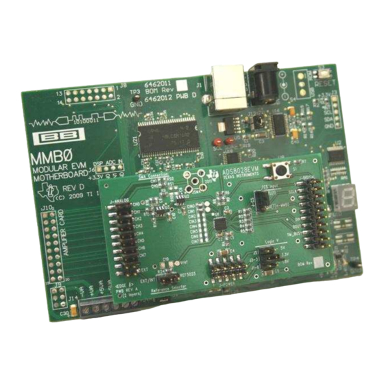
Figure 1. ADS8028EVM-PDK
Table 1. EVM-Compatible Device Data Sheets
Device
ADS8028
OPA836
REF5025
Copyright © 2012–2016, Texas Instruments Incorporated
SBAU198A – April 2012 – Revised February 2016
ADS8028EVM-PDK
Literature Number
SBAS549
SLOS712
SBOS410
ADS8028EVM-PDK
User's Guide
1
Advertisement
Table of Contents

Related Manuals for Texas Instruments ADS8028EVM-PDK


Summary of Contents for Texas Instruments ADS8028EVM-PDK
-
Page 1: Ads8028Evm-Pdk
ADS8028EVM-PDK Figure 1. ADS8028EVM-PDK This user's guide describes the characteristics, operation, and use of the ADS8028EVM-PDK. This evaluation module and performance development kit (EVM-PDK) is an evaluation system for the ADS8028, a 12-bit, 1-MSPS, 8-channel, successive approximation register (SAR) analog-to-digital converter (ADC). -
Page 2: Table Of Contents
Contents ....................... EVM Overview ........................EVM Setup ..................ADS8028EVM Hardware Details ................Using the ADS8028EVM-PDK with ADCPro ..................Schematics and Bill of Materials List of Figures ......................ADS8028EVM-PDK ................... Jumper Locations and Default Settings ....................Headers and Pin Numbers ................... -
Page 3: Evm Overview
EVM Overview The ADS8028EVM-PDK is designed to evaluate the ADS8028. The ADS8028 is a 12-bit, 8-channel, multiplexed, SAR ADC, with a maximum throughput rate of 1 MSPS. The ADS8028 also offers an internal 2.5-V voltage reference and internal temperature sensor with 0.25°C resolution. The ADS8028EVM allows access to every pin of the converter and makes it easy to connect the ADS8028 SPI™-compatible serial... -
Page 4: Evm Setup
Only one of the digital interface jumpers (J-1, J-3, or J-5) should be shorted at a time to prevent large reverse currents that could potentially damage voltage regulators on the MMB0 motherboard. ADS8028EVM-PDK SBAU198A – April 2012 – Revised February 2016 Submit Documentation Feedback Copyright © 2012–2016, Texas Instruments Incorporated... - Page 5 EVM Setup www.ti.com ADS8028EVM-PDK Kit Operation To prepare to evaluate the ADS8028 with the ADS8028EVM-PDK, complete the following steps: 1. Verify the ADS8028EVM jumper settings from the factory as shown in Figure 2 and also listed in Table 2. Install ADCPro and the ADS8028EVM plug-in software. Complete hardware connections and driver...
-
Page 6: Ads8028Evm Hardware Details
All ADS8028 analog inputs are single-ended and connect between the even and odd pins on the J-ANALOG header. All odd pins on J-ANALOG are connected to AGND. ADS8028EVM-PDK SBAU198A – April 2012 – Revised February 2016 Submit Documentation Feedback Copyright © 2012–2016, Texas Instruments Incorporated... -
Page 7: Analog Input Header Schematic
(The channel 0 input connects to J- ANALOG.1-2, channel 1 input connects to J-ANALOG.3-4, etc.). SBAU198A – April 2012 – Revised February 2016 ADS8028EVM-PDK Submit Documentation Feedback Copyright © 2012–2016, Texas Instruments Incorporated... -
Page 8: Digital Interface Header Schematic
DIGITAL.1 or J-DIGITAL.7 (default) through the J-CS jumper. Ensure that the J-CS jumper is positioned to route CS to J-DIGITAL.7 (short pins J-CS.1-2) for proper SPI communication when using the ADS8028EVM-PDK. Additionally, the S1 push-button switch allows the user to manually reset and power- down the ADS8028 and OPA836 op amps on the ADS8028EVM while the button is held. -
Page 9: Power Header Schematic
ADS8028EVM to 5.5 V. The digital supply voltage should not exceed the analog supply voltage. SBAU198A – April 2012 – Revised February 2016 ADS8028EVM-PDK Submit Documentation Feedback Copyright © 2012–2016, Texas Instruments Incorporated... -
Page 10: Evm Voltage Reference Schematic
Providing an external source prior to this communication draws additional current from the external source. The ADS8028 internal protection circuitry limits this current to 20 mA. ADS8028EVM-PDK SBAU198A – April 2012 – Revised February 2016 Submit Documentation Feedback Copyright © 2012–2016, Texas Instruments Incorporated... -
Page 11: Using The Ads8028Evm-Pdk With Adcpro
Using the ADS8028EVM-PDK with ADCPro www.ti.com Using the ADS8028EVM-PDK with ADCPro This section covers the use of the ADS8028EVM-PDK plug-in for ADCPro. For general ADCPro software use and instructions, refer to the ADCPro User's Guide. The ADS8028EVM-PDK plug-in for ADCPro provides complete control over all ADS8028 settings. It... -
Page 12: Adcpro: Channel Selection Tab
Using the ADS8028EVM-PDK with ADCPro www.ti.com Channel Selection Tab The ADS8028 can acquire data from one to eight channels, sequentially. The Channel Select tab provides the control to select which channels are sampled. A channel is selected to be sampled if a check mark is seen in the box corresponding to the channel number. -
Page 13: Schematics And Bill Of Materials
Using the ADS8028EVM-PDK with ADCPro www.ti.com The Reference Source control selects between the ADS8028 internal voltage reference (INT) and an external voltage reference source (EXT). Selecting EXT disables the internal voltage reference and allows the user to specify the applied reference voltage in the Reference Voltage indicator to display the correct voltage output values. -
Page 14: Ads8028Evm Bill Of Materials
IC, Precision Voltage Reference, 2.5V, SO-8 Texas Instruments REF5025AID — IC, EEPROM, 256KBIT, 400KHZ, TSSOP-8 Microchip 24AA256-I/ST Technology — — Shunt, 100-mil, Black 969102-0000-DA ADS8028EVM-PDK SBAU198A – April 2012 – Revised February 2016 Submit Documentation Feedback Copyright © 2012–2016, Texas Instruments Incorporated... - Page 15 Schematics and Bill of Materials www.ti.com Schematic SBAU198A – April 2012 – Revised February 2016 ADS8028EVM-PDK Submit Documentation Feedback Copyright © 2012–2016, Texas Instruments Incorporated...
- Page 16 Page ..• Replaced reference of adapter to external supply in two places in the ADS8028EVM-PDK Kit Operation section. NOTE: Page numbers for previous revisions may differ from page numbers in the current version. Revision History SBAU198A – April 2012 – Revised February 2016 Submit Documentation Feedback Copyright ©...
- Page 17 STANDARD TERMS AND CONDITIONS FOR EVALUATION MODULES Delivery: TI delivers TI evaluation boards, kits, or modules, including any accompanying demonstration software, components, or documentation (collectively, an “EVM” or “EVMs”) to the User (“User”) in accordance with the terms and conditions set forth herein. Acceptance of the EVM is expressly subject to the following terms and conditions.
- Page 18 FCC Interference Statement for Class B EVM devices NOTE: This equipment has been tested and found to comply with the limits for a Class B digital device, pursuant to part 15 of the FCC Rules. These limits are designed to provide reasonable protection against harmful interference in a residential installation.
- Page 19 【無線電波を送信する製品の開発キットをお使いになる際の注意事項】 開発キットの中には技術基準適合証明を受けて いないものがあります。 技術適合証明を受けていないもののご使用に際しては、電波法遵守のため、以下のいずれかの 措置を取っていただく必要がありますのでご注意ください。 1. 電波法施行規則第6条第1項第1号に基づく平成18年3月28日総務省告示第173号で定められた電波暗室等の試験設備でご使用 いただく。 2. 実験局の免許を取得後ご使用いただく。 3. 技術基準適合証明を取得後ご使用いただく。 なお、本製品は、上記の「ご使用にあたっての注意」を譲渡先、移転先に通知しない限り、譲渡、移転できないものとします。 上記を遵守頂けない場合は、電波法の罰則が適用される可能性があることをご留意ください。 日本テキサス・イ ンスツルメンツ株式会社 東京都新宿区西新宿6丁目24番1号 西新宿三井ビル 3.3.3 Notice for EVMs for Power Line Communication: Please see http://www.tij.co.jp/lsds/ti_ja/general/eStore/notice_02.page 電力線搬送波通信についての開発キットをお使いになる際の注意事項については、次のところをご覧くださ い。http://www.tij.co.jp/lsds/ti_ja/general/eStore/notice_02.page SPACER EVM Use Restrictions and Warnings: 4.1 EVMS ARE NOT FOR USE IN FUNCTIONAL SAFETY AND/OR SAFETY CRITICAL EVALUATIONS, INCLUDING BUT NOT LIMITED TO EVALUATIONS OF LIFE SUPPORT APPLICATIONS.
- Page 20 Notwithstanding the foregoing, any judgment may be enforced in any United States or foreign court, and TI may seek injunctive relief in any United States or foreign court. Mailing Address: Texas Instruments, Post Office Box 655303, Dallas, Texas 75265 Copyright © 2015, Texas Instruments Incorporated...
- Page 21 IMPORTANT NOTICE Texas Instruments Incorporated and its subsidiaries (TI) reserve the right to make corrections, enhancements, improvements and other changes to its semiconductor products and services per JESD46, latest issue, and to discontinue any product or service per JESD48, latest issue.
Need help?
Do you have a question about the ADS8028EVM-PDK and is the answer not in the manual?
Questions and answers