
Subscribe to Our Youtube Channel
Related Manuals for Belden Hirschmann EAGLE20


Summary of Contents for Belden Hirschmann EAGLE20
- Page 1 User Manual Installation Industrial Security Router EAGLE20/30 Installation EAGLE20/30 Technical support Release 11 09/2020 https://hirschmann-support.belden.com...
- Page 2 The naming of copyrighted trademarks in this manual, even when not specially indicated, should not be taken to mean that these names may be considered as free in the sense of the trademark and tradename protection law and hence that they may be freely used by anyone. ©...
-
Page 3: Table Of Contents
Contents Safety instructions About this manual Description General device description Device name and product code Device views 1.3.1 Front view 1.3.2 Rear view Power supply 1.4.1 Supply voltage with the characteristic value K9 1.4.2 Supply voltage with the characteristic value KK 1.4.3 Supply voltage with the characteristic value CC Ethernet ports 1.5.1 10/100 Mbit/s twisted pair port... - Page 4 2.3.1 Installing the device onto the DIN rail 2.3.2 Grounding the device Installing an SFP transceiver (optional) Connecting the terminal blocks 2.5.1 Supply voltage with the characteristic value K9 2.5.2 Supply voltage with the characteristic value KK 2.5.3 Supply voltage with the characteristic value CC 2.5.4 Signal contact Operating the device Connecting data cables...
-
Page 5: Safety Instructions
Safety instructions WARNING UNCONTROLLED MACHINE ACTIONS To avoid uncontrolled machine actions caused by data loss, configure all the data transmission devices individually. Before you start any machine which is controlled via data transmission, be sure to complete the configuration of all data transmission devices. Failure to follow these instructions can result in death, serious injury, or equipment damage. - Page 6 Device casing Only technicians authorized by the manufacturer are permitted to open the casing. Never insert pointed objects (narrow screwdrivers, wires, etc.) into the device or into the connection terminals for electric conductors. Do not touch the connection terminals. ...
- Page 7 National and international safety regulations Verify that the electrical installation meets local or nationally applicable safety regulations. Grounding the device Grounding the device is by means of a separate ground connection on the device. Ground the device before connecting any other cables. ...
- Page 8 Device variant Requirements All variants All of the following requirements are complied with: The supply voltage corresponds to the voltage specified on the type plate of the device. The power supply conforms to overvoltage category I or II. ...
- Page 9 Supply voltage The supply voltage is connected to the device casing through protective elements exclusively. Instructions for Use in Hazardous Locations Note: The following information applies only to models without WAN ports. See “Device name and product code” on page 16. SUITABLE FOR USE IN CLASS I, DIVISION 2, GROUPS A, B, C AND D HAZARDOUS LOCATIONS, OR NONHAZARDOUS LOCATIONS ONLY.
- Page 10 Explosive Atmosphere Ordinary Location, Non-Hazardous Area, non-explosive atmosphere Class I, Division 2 Groups A, B, C, D Hazardous Location USB connection: Equipment with non-incendive field wiring parameters. EAGLE20/30 USB entity parameters: = 5.5 V = 1.25 A = 10 µF = 10 µH For usage with Hirschmann USB devices certified and labelled according Class I Div 2 hazardous location requirements such...
- Page 11 For Use in Hazardous Locations Class I Division 2 Groups A, B ,C ,D: Only allowed for EAGLE20/30 model No´s. which are individually labelled “FOR USE IN HAZARDOUS LOCATIONS” Non-incendive field wiring circuits must be wired in accordance with the National Electrical Code (NEC), NFPA 70 , article 501. The earth conductor must be at least the same wire size (mm²...
- Page 12 CE marking The labeled devices comply with the regulations contained in the following European directive(s): Device variant Directive All variants 2011/65/EU and 2015/863/EU (RoHS) Directive of the European Parliament and of the Council on the restriction of the use of certain hazardous substances in electrical and electronic equipment.
- Page 13 Supplier's Declaration of Conformity 47 CFR § 2.1077 Compliance Information EAGLE20/30 U.S. Contact Information Belden – St. Louis 1 N. Brentwood Blvd. 15th Floor St. Louis, Missouri 63105, United States Phone: 314.854.8000 This device complies with part 15 of the FCC Rules. Operation is subject...
-
Page 14: About This Manual
About this manual The “Installation” user manual contains a device description, safety instructions, a description of the display, and the other information that you need to install the device. The Industrial HiVision Network Management software provides you with additional options for smooth configuration and monitoring: ... -
Page 15: Description
Description General device description You can choose from between a wide range of variants. You have the option to set up your device individually based on different criteria: Number of ports Transmission speed Types of connectors Temperature range ... -
Page 16: Device Name And Product Code
You have numerous options of combining the device characteristics. You can determine the possible combinations using the configurator which is available in the Belden E-Catalog (www.e-catalog.beldensolutions.com) on the web page of the device. Item Product... - Page 17 Item Product Characteristic Description characteristic value 24 ... 25 Certifications Note: You will find detailed information on the certificates and declarations applying to your device in a separate overview. See table 5 on page 18. Table 4: Device name and product code Installation EAGLE20/30 Release 11 09/2020...
- Page 18 Application case Certificates and Characteristic value declarations Standard applications UL 508 EN 60950-1 EN 61131-2 UL 60950-1 Oil and gas applications ISA 12.12.01 – Class I, Div. 2 Substation applications IEC 61850-3 IEEE 1613 Navy applications Railway applications EN 50121-4 Table 5: Assignment: application cases, certificates and declarations, characteristic values a.
-
Page 19: Device Views
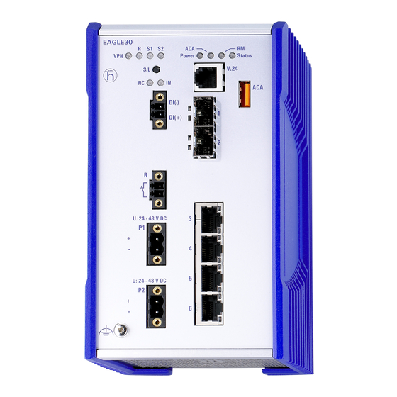
Device views 1.3.1 Front view EAGLE30-0402206TT9H2SCC... LED display elements for device status V.24 interface USB port 2 × SFP slot (optional) 4 × Fast Ethernet ports 2 × SHDSL port (optional) LED display elements for the status of the SHDSL ports Grounding screw Supply voltage connection alternatively,... -
Page 20: Rear View
1.3.2 Rear view Slot for the SD card Knurled screw Power supply 1.4.1 Supply voltage with the characteristic value K9 For the power supply of the device, a 3-pin terminal block is available. For further information see “Supply voltage with the characteristic value K9” on page 1.4.2 Supply voltage with the characteristic value KK... -
Page 21: Ethernet Ports
Ethernet ports You can connect end devices and other segments to the device ports using twisted pair cables or optical fibers (F/O). You find information on pin assigments for making patch cables here: See “Pin assignments” on page 22. 1.5.1 10/100 Mbit/s twisted pair port This port is an RJ45 socket. -
Page 22: 100/1000 Mbit/S Twisted Pair Port (Optional)
1.5.3 100/1000 Mbit/s twisted pair port (optional) Note: The following information applies only to device variants with HiSecOS, software versions 01.2.00 and higher. You set up this connection using the following SFP transceivers, which you insert into the SFP slot of the 100/1000 Mbit/s F/O port: ... -
Page 23: Wan Port (Optional)
M12 4-pin (D coded) Data Positive V Negative V TX− Positive V RX− Negative V M12 8-pin (X-coded) 10/100 Mbit/s 1000 Mbit/s BI_DB+ Negative V RX− BI_DB− Negative V BI_DA+ Positive V TX− BI_DA− Positive V — BI_DC+ — — BI_DC−... -
Page 24: Display Elements
Display elements After the supply voltage is set up, the software starts and initializes itself. Afterwards, the device performs a self-test. During this process, various LEDs light up. 1.7.1 Device state These LEDs provide information about conditions which affect the operation of the whole device. -
Page 25: Digital Input (Optional)
1.7.2 Digital input (optional) Note: Only for supply voltage with the following characteristic values: Display Color Activity Meaning The support of the function is dependent on the software release. Software support for the function is unimplemented at the time of publishing this manual. 1.7.3 Port state Ethernet ports... -
Page 26: Additional Status Information (Optional)
1.7.4 Additional status information (optional) Note: Only for supply voltage with the following characteristic values: VPN RD S1 S2 Display Color Activity Meaning VPN connections Green Lights up The LED lights up green when one or more VPN connections are active and are in the up state. -
Page 27: Management Interfaces
Management interfaces 1.8.1 V.24 interface (external management) Note: For information about the position on the device see “Front view” on page A serial interface is provided on the RJ11 socket (V.24 interface) for the local connection of an external management station (VT100 terminal or PC with corresponding terminal emulation). -
Page 28: Usb Interface
1.8.3 USB interface Note: For information about the position on the device see “Front view” on page The USB socket has an interface for the local connection of an AutoConfiguration Adapter ACA22. It is used for saving/loading the configuration data and diagnostic information, and for loading the software. The USB interface has the following properties: ... -
Page 29: Input/Output Interfaces
Input/output interfaces 1.9.1 Signal contact Figure 2: Signal contact: 2-pin terminal block with screw locking In the state on delivery, the signal contact indicates the device status. It can be configured using the device management. 1.9.2 Digital input (optional) Note: Only for supply voltage with the following characteristic values: ... -
Page 30: Installation
Installation The devices have been developed for practical application in a harsh industrial environment. On delivery, the device is ready for operation. Perform the following steps to install and configure the device: Checking the package contents Installing the SD card (optional) ... -
Page 31: Installing And Grounding The Device
Installing and grounding the device WARNING FIRE HAZARD Install the device in a fire enclosure according to EN 60950-1. Failure to follow these instructions can result in death, serious injury, or equipment damage. WARNING Only for device variants featuring supply voltage with the characteristic value K9 or KK: ELECTRIC SHOCK Install this device solely in a switch cabinet or in an operating site with... -
Page 32: Grounding The Device
Figure 4: Mounting on the DIN rail 2.3.2 Grounding the device WARNING ELECTRIC SHOCK Ground the device before connecting any other cables. Failure to follow these instructions can result in death, serious injury, or equipment damage. The housing is grounded via the separate ground screw on the bottom left of the front panel. -
Page 33: Installing An Sfp Transceiver (Optional)
Installing an SFP transceiver (optional) Prerequisites: Exclusively use Hirschmann SFP transceivers. See “Accessories” on page 54. Figure 5: Installing SFP transceivers: Installation sequence Proceed as follows: Take the SFP transceiver out of the transport packaging (1). Remove the protection cap from the SFP transceiver (2). ... -
Page 34: Connecting The Terminal Blocks
Connecting the terminal blocks WARNING ELECTRIC SHOCK Never insert pointed objects (narrow screwdrivers, wires, etc.) into the device or into the connection terminals for electric conductors. Do not touch the connection terminals. Before connecting the electrical wires, always verify that the requirements listed are complied with. -
Page 35: Supply Voltage With The Characteristic Value Kk
For the supply voltage to be connected, perform the following steps: Remove the power connector from the device. Connect the wires according to the pin assignment on the device with the clamps. Fasten the wires connected by tightening the terminal screws. 2.5.2 Supply voltage with the characteristic value KK You have the option of supplying the supply voltage redundantly, without... -
Page 36: Supply Voltage With The Characteristic Value Cc
2.5.3 Supply voltage with the characteristic value CC You have the option of supplying the supply voltage redundantly, without load distribution. Both supply voltage inputs are uncoupled. − Figure 8: Supply voltage with the characteristic value CC: 2-pin terminal block with screw locking Type of the voltages Specification of the supply... -
Page 37: Operating The Device
Operating the device WARNING ELECTRIC SHOCK Before connecting the electrical wires, always verify that the requirements listed are complied with. See “Requirements for connecting electrical wires” on page 7. Failure to follow these instructions can result in death, serious injury, or equipment damage. -
Page 38: 100/1000 Mbit/S F/O Port (Optional)
2.7.2 100/1000 Mbit/s F/O port (optional) Verify that you connect LH ports only with LH ports, SX ports only with SX ports, and LX ports only with LX ports. Connect the data cables according to your requirements. See “Ethernet ports” on page 21. 2.7.3 WAN port (optional) Note: In general, you should adhere to the following recommendations for... -
Page 39: Making Basic Settings
Making basic settings Note: 2 or more devices configured with the same IP address can cause unpredictable operation of your network. Install and maintain a process that assigns a unique IP address to every device in the network. The IP parameters must be entered when the device is installed for the first time. -
Page 40: First Login (Password Change)
Log on to the device again with your new password. Note: If you lost your password, then use the System Monitor to reset the password. For further information see: https://hirschmann-support.belden.com/en/kb/required-password-change- new-procedure-for-first-time-login Installation EAGLE20/30 Release 11 09/2020... -
Page 41: Monitoring The Ambient Air Temperature
Monitoring the ambient air temperature Operate the device below the specified maximum ambient air temperature exclusively. See “General technical data” on page 44. The ambient air temperature is the temperature of the air at a distance of 2 in (5 cm) from the device. It depends on the installation conditions of the device, e.g. -
Page 42: Disassembly
Disassembly Removing the device WARNING ELECTRIC SHOCK Disconnect the grounding only after disconnecting all other cables. Failure to follow these instructions can result in death, serious injury, or equipment damage. Disconnect the data cables. Disable the supply voltage. ... -
Page 43: Removing An Sfp Transceiver (Optional)
Removing an SFP transceiver (optional) Figure 10: De-installing SFP transceivers: De-installation sequence Proceed as follows: Open the locking mechanism of the SFP transceiver (1). Pull the SFP transceiver out of the slot via the open locking mechanism (2). ... -
Page 44: Technical Data
Technical data General technical data Weight EAGLE..-..999S.. approx. 2.65 lb (1.2 kg) EAGLE..-..999T.. approx. 3.31 lb (1.5 kg) EAGLE..-..999E.. EAGLE..-..9H2S.. EAGLE..-..9H2E.. approx. 4.19 lb (1.9 kg) EAGLE..-..9H2T.. Power supply See “Requirements for connecting electrical wires” on page 7. Supply voltage Nominal voltage DC 24 V ... - Page 45 Climatic Ambient air temperature Devices with operating temperature conditions characteristic value S (standard): during 0 °C ... +60 °C (+32 °F ... +140 °F) operation Devices with operating temperature characteristic value E and T (extended): −40 °C ... +70 °C Humidity 5 % ...
- Page 46 SHDSL range Profile Data rate Data rate per port Power Region Configuration Range per link (with activated (dBm) (m (ft)) (kbit/s) link aggregation) (kbit/s) 5696 11392 13.5 North America 32-TCPAM 2000 (6562) (Annex A) 3072 6144 13.5 North America 32-TCPAM 2800 (9186) (Annex_A)
- Page 47 Dimension drawings 114,7 6,55 4.52 inch 0.26 2.76 89,9 3.54 Figure 11: Dimensions of the device variants without WAN ports with operating characteristic value S. For the characteristic value, see “Device name and product code” on page 114,7 6,55 4.52 inch 0.26...
- Page 48 inch 4.21 120,85 4.76 6,55 114,7 0.26 4.52 2.76 121,95 Figure 13: Dimensions of the device variants with WAN ports with operating characteristic value S. For the characteristic value, see “Device name and product code” on page 115,97 6,55 114,7 4.57 0.26 4.52...
- Page 49 EMC and immunity Note: You will find detailed information on the certificates and declarations applying to your device in a separate overview. See table 5 on page 18. EMC interference Standard Navy applications Railway Substation emission applications applications applications Radiated emission EN 55032 Class A...
- Page 50 EMC interference Standard Navy applications Railway Substation immunity applications applications applications EN 61000-4-3 80 MHz ... 2700 MHz — — 20 V/m — IEEE 1613 80 MHz ... 1000 MHz — — — 35 V/m Fast transients (burst) EN 61000-4-4 AC/DC supply connection ±...
- Page 51 EMC interference Standard Navy applications Railway Substation immunity applications applications applications Damped oscillation - AC/DC supply connection EN 61000-4-12 line/ground — — — 2.5 kV IEEE C37.90.1 EN 61000-4-12 line/line — — — 1 kV IEEE C37.90.1 Damped oscillation - data line EN 61000-4-12 line/ground —...
- Page 52 Network range Note: The line lengths specified for the transceivers apply for the respective fiber data (fiber attenuation and BLP/dispersion). Product Wave Fiber System Example Fiber code length attenu- for F/O line attenu- dispersion M-SFP-... ation length ation -SX/LC... MM 850 nm 50/125 µm 0-7.5 dB 0-550 m...
- Page 53 Product Wave Fiber System Example Fiber BLP/ code length attenu- for F/O line attenu- dispersion M-FAST- ation length ation SFP-... -MM/LC... MM 1310 nm 50/125 µm 0-8 dB 0-5 km 1.0 dB/km 800 MHz×km -MM/LC... MM 1310 nm 62.5/125 µm 0-11 dB 0-4 km 1.0 dB/km 500 MHz×km...
- Page 54 Scope of delivery Number Article 1 × Device 2 × 2-pin terminal block for signal contact and input (only for device variants featuring supply voltage with characteristic value K9 and CC) 1 × 2-pin terminal block for signal contact (only for device variants featuring supply voltage with characteristic value KK) 1 ×...
- Page 55 Gigabit Ethernet SFP transceiver Order number M-SFP-TX/RJ45 943 977-001 M-SFP-TX/RJ45 EEC 942 161-001 The following operating conditions apply to twisted pair transceivers: Usable with: - HiOS as of software version 03.0.00 - Classic Switch software, as of software version 04.1.00. - HiSecOS as of software version 01.2.00 Do not use with the following devices: - SPIDER II- MSP/MSM...
- Page 56 Fast Ethernet SFP transceiver Order number M-FAST SFP-TX/RJ45 942 098-001 M-FAST SFP-TX/RJ45 EEC 942 098-002 The following operating conditions apply to twisted pair transceivers: Usable with: - HiOS as of software version 03.0.00 - for PRP ports on RSP devices, as of software version 02.0.01 - for PRP ports on EES devices, as of software version 02.0.02 - Classic switch software as of software version 08.0.00 - HiSecOS as of software version 01.2.00...
- Page 57 Underlying technical standards Designation CSA C22.2 No. 142 Canadian National Standard(s) – Process Control Equipment – Industrial Products ISA 12.12.01 Nonincendive Electrical Equipment for Use in Class I and II, Division 2 and Class III, Divisions 1 and 2 Hazardous (Classified) Locations CAN/CSA C22.2 Non-incendive Electrical Equipment for Use in Class I, Division 2 No.
-
Page 58: A Further Support
You find the addresses of our partners on the Internet at http://www.hirschmann.com. A list of local telephone numbers and email addresses for technical support directly from Hirschmann is available at https://hirschmann-support.belden.com. This site also includes a free of charge knowledge base and a software download section. Hirschmann Competence Center... - Page 59 Installation EAGLE20/30 Release 11 09/2020...
Need help?
Do you have a question about the Hirschmann EAGLE20 and is the answer not in the manual?
Questions and answers