
Related Manuals for Belden HIRSCHMANN EAGLE40-03


Summary of Contents for Belden HIRSCHMANN EAGLE40-03
- Page 1 User Manual Installation Industrial Security Router EAGLE40-03 EAGLE40-07 Installation EAGLE40 Technical support Release 02 08/2020 https://hirschmann-support.belden.com...
- Page 2 The naming of copyrighted trademarks in this manual, even when not specially indicated, should not be taken to mean that these names may be considered as free in the sense of the trademark and tradename protection law and hence that they may be freely used by anyone. ©...
-
Page 3: Table Of Contents
Contents Important Information Safety instructions About this manual Description General device description Device name and product code Device views EAGLE40-03 1.3.1 Front view Device views EAGLE40-07 1.4.1 Front view 1.4.2 Right side view 1.4.3 Left side view Power supply Ethernet ports 1.6.1 10/100/1000 Mbit/s twisted pair port 1.6.2 1000 Mbit/s F/O port 1.6.3 Pin assignments... - Page 4 Checking the package contents Installing and grounding the device 2.2.1 Installing the device onto the DIN rail 2.2.2 Grounding the device Installing an SFP transceiver (optional) Connecting the terminal blocks 2.4.1 Connecting the power supply and signal lines 2.4.2 Wiring the digital input (optional) Operating the device Connecting data cables 2.6.1 Twisted Pair ports...
-
Page 5: Important Information
Important Information Notice: Read these instructions carefully, and look at the equipment to become familiar with the device before trying to install, operate, or maintain it. The following special messages may appear throughout this documentation or on the equipment. The message warns of potential hazards or calls attention to information that clarifies or simplifies a procedure. -
Page 6: Safety Instructions
Safety instructions WARNING UNCONTROLLED MACHINE ACTIONS To avoid uncontrolled machine actions caused by data loss, configure all the data transmission devices individually. Before you start any machine which is controlled via data transmission, be sure to complete the configuration of all data transmission devices. Failure to follow these instructions can result in death, serious injury, or equipment damage. - Page 7 Device casing Only technicians authorized by the manufacturer are permitted to open the casing. Never insert pointed objects (narrow screwdrivers, wires, etc.) into the device or into the connection terminals for electric conductors. Do not touch the connection terminals. ...
- Page 8 All of the following requirements are complied with: The electrical wires are voltage-free. The cables used are permitted for the temperature range of the application case. The voltage connected complies with the requirements for a safety extra-low voltage (SELV) as per IEC/EN 60950-1 or IEC/EN 62368-1.
- Page 9 Cet équipement est un dispositif de type ouvert qui doit être installé dans une enveloppe adaptée à l’environnement afin que le dispositif soit accessible uniquement avec l’utilisation d’un outil. Ta: -40 °F ... +158 °F (-40 °C ... +70 °C), temperature code: T4 WARNING –...
- Page 10 Special conditions for safe use Install the device according to EN 60664-1 in an environment not exceeding degree of pollution 2. Install the basic devices and media modules in a suitable enclosure providing a degree of protection of at least IP54 according to EN 60079-0, taking into account the ambient conditions under which the equipment will be used.
- Page 11 Supplier's Declaration of Conformity 47 CFR § 2.1077 Compliance Information EAGLE40 U.S. Contact Information Belden – St. Louis 1 N. Brentwood Blvd. 15th Floor St. Louis, Missouri 63105, United States Phone: 314.854.8000 This device complies with part 15 of the FCC Rules. Operation is subject...
-
Page 12: About This Manual
About this manual The “Installation” user manual contains a device description, safety instructions, a description of the display, and the other information that you need to install the device. The manual is available for download on the Internet: https:// www.doc.hirschmann.com Installation EAGLE40 Release 02 08/2020... -
Page 13: Key
The symbols used in this manual have the following meanings: Listing Work step Subheading Installation EAGLE40 Release 02 08/2020... -
Page 14: Description
You have numerous options of combining the device characteristics. You can determine the possible combinations using the configurator which is available in the Belden Online Catalog (https://catalog.belden.com) on the web page of the device. Installation EAGLE40... - Page 15 Item Product Character Description characteristic istic value 1 ... 7 Device EAGLE40 Security Router and Firewall (hyphen) – 9 ... 10 Number: 3 × 1000 Mbit/s Gigabit Ethernet ports 7 × 1000 Mbit/s 11 ... 13 Configuration of the 3 × Twisted pair RJ45 uplink ports 1 ×...
- Page 16 Application case Certificates Characteristic value declarations Standard ATEX applications EN 50121-4 EN 61131-2 EN 62368-1 IEC 61850-3 IEEE 1613 ANSI/UL 121201 UL 62368 Table 5: Assignment: application cases, certificates and declarations, characteristic values a. X = Certificate or declaration present Installation EAGLE40 Release 02 08/2020...
-
Page 17: Device Views Eagle40-03
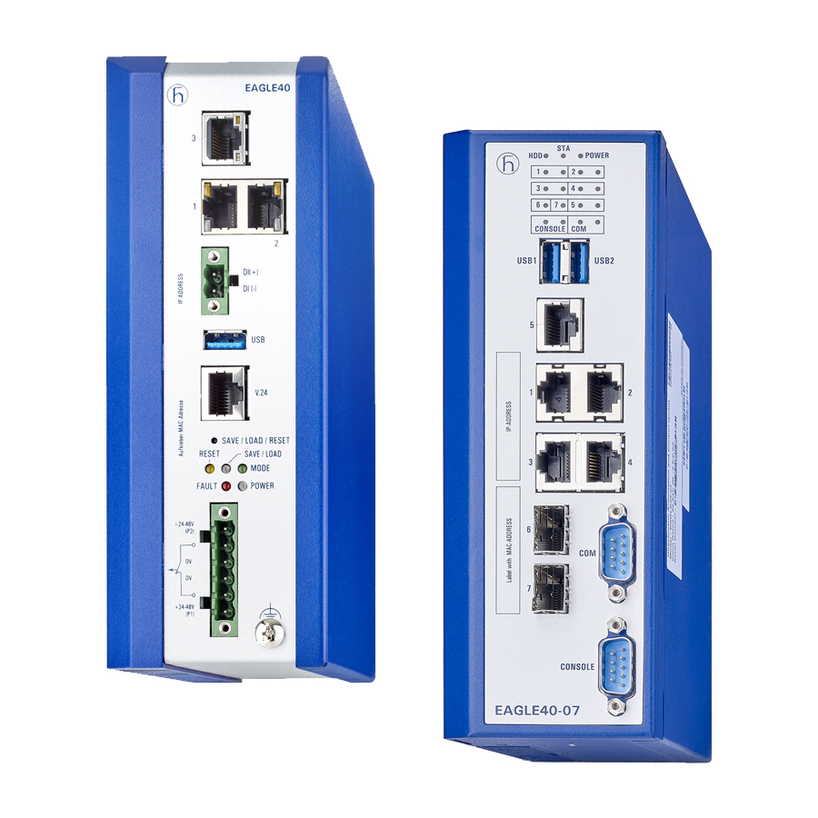
Device views EAGLE40-03 1.3.1 Front view Ethernet port (RJ45) for 10/100/1000 Mbit/s Twisted pair connections 1 × SFP slot for 1000 Mbit/s fiber optic connections V.24 interface LED display element (EAGLE40-033T1...) LED display element (EAGLE40-03106...) Grounding screw 6-pin terminal block connection Save/Load/Reset button Label area for MAC address USB Interface... -
Page 18: Device Views Eagle40-07
Device views EAGLE40-07 1.4.1 Front view LED display element 2 × USB interface 5 × Gigabit Ethernet ports (RJ45) for 10/100/1000 Mbit/s Twisted pair connections COM port (DB9 port) CONSOLE port (DB9 port) 2 × SFP ports for 1000 Mbit/s fiber optic connections Installation EAGLE40 Release 02 08/2020... -
Page 19: Right Side View
1.4.2 Right side view 6-pin terminal block connection Grounding screw Installation EAGLE40 Release 02 08/2020... -
Page 20: Left Side View
1.4.3 Left side view Save/Load/Reset button Power supply A 6-pin, screwable terminal block is available for the redundant supply to the device. For further information: See “Connecting the power supply and signal lines” on page 31. Ethernet ports You can connect end devices and other segments to the device ports using twisted pair cables or optical fibers (F/O). -
Page 21: 10/100/1000 Mbit/S Twisted Pair Port
1.6.1 10/100/1000 Mbit/s twisted pair port This port is an RJ45 socket. The 10/100/1000 Mbit/s twisted pair port offers you the ability to connect network components according to the IEEE 802.3 10BASE-T/100BASE-TX/ 1000BASE-TX standard. This port supports: Autonegotiation Autopolarity ... -
Page 22: Display Elements
Display elements After the supply voltage is set up, the software starts and initializes itself. Afterwards, the device performs a self-test. During this process, various LEDs light up. 1.7.1 Device state EAGLE40-03 These LEDs provide information about conditions which affect the operation of the whole device. -
Page 23: Port State Eagle40-03
Display Color Activity Meaning Router redun- — None No router redundancy configured dancy Green Lights up The device is in the Router Redundancy Master mode. Flashing The device is in the Router Redundancy Backup mode. 1.7.2 Port state EAGLE40-03 Ethernet ports ... -
Page 24: Management Interfaces 1.8.1 V.24 Interface (External Management)
Display Color Activity Meaning Link status — None No link is established. (LED on the left) Yellow Lights up Link has been established. Flashing The connection is active. Speed — None Operating as a 10-Mbit/s connection (LED on the right) Green Lights up Operating as a Gigabit connection Yellow Lights up... -
Page 25: Db9 Port
RJ45 RJ45 Figure 1: Pin assignment of the V.24 interface and the DB9 connector 1.8.2 DB9 port Note: EAGLE40-07 devices have a DB9 port for console access. The port is labeled "CONSOLE". The "COM" port has no functionality in the current release. -
Page 26: Input/Output Interfaces
Voltage not potential-separated Supported file system: FAT32 Figure Operation VCC (VBus) − Data + Data Ground (GND) Table 6: Pin assignment of the USB interface Note: Please note that in EAGLE40-07 devices, you can currently only use 1 of the 2 USB interfaces. Which one of the USB interfaces you decide to use does not make a difference. - Page 27 You will find detailed information on possible applications and the configuration of the digital input in the software user documentation. You will find the software user documentation as PDF files on the Internet at https:// www.doc.hirschmann.com Installation EAGLE40 Release 02 08/2020...
-
Page 28: Installation
Installation The devices have been developed for practical application in a harsh industrial environment. On delivery, the device is ready for operation. Perform the following steps to install and configure the device: Checking the package contents Installing and grounding the device ... -
Page 29: Grounding The Device
Note: The overall shield of a connected shielded twisted pair cable is connected to the ground connector on the front panel as a conductor. To mount the device onto a horizontally mounted 35 mm DIN rail according to DIN EN 60715, proceed as follows: ... -
Page 30: Installing An Sfp Transceiver (Optional)
Installing an SFP transceiver (optional) Prerequisites: Exclusively use Hirschmann SFP transceivers. See “Accessories” on page 48. Figure 4: Installing SFP transceivers: Installation sequence Proceed as follows: Take the SFP transceiver out of the transport packaging (1). Remove the protection cap from the SFP transceiver (2). ... -
Page 31: Connecting The Power Supply And Signal Lines
The supply voltage is connected to the device casing through protective elements exclusively. 2.4.1 Connecting the power supply and signal lines Power supply connection 1 24 V DC 0 V DC Connection for the signal contact Power supply connection 2 0 V DC 24 V DC Table 7:... -
Page 32: Wiring The Digital Input (Optional)
Remove the power connector from the device. Connect the wires according to the pin assignment on the device with the clamps. Fasten the wires connected by tightening the terminal screws. Signal contact (optional) Connect the wires according to the pin assignment on the device with the clamps. -
Page 33: Connecting Data Cables
Note: Relevant for North America: The torque for tightening the supply voltage terminal block on the EAGLE40-03 devices is 7 lb-in (0.79 Nm). The torque for tightening the signal contact and input terminal block on the EAGLE40-03 devices is 7 lb-in (0.79 Nm). ... -
Page 34: Making Basic Settings
Making basic settings Note: 2 or more devices configured with the same IP address can cause unpredictable operation of your network. Install and maintain a process that assigns a unique IP address to every device in the network. The IP parameters must be entered when the device is installed for the first time. - Page 35 Log on to the device again with your new password. Note: If you lost your password, then use the System Monitor to reset the password. For further information see: https://hirschmann-support.belden.com/en/kb/required-password-change- new-procedure-for-first-time-login Installation EAGLE40 Release 02 08/2020...
-
Page 36: Monitoring The Ambient Air Temperature
Monitoring the ambient air temperature Operate the device below the specified maximum ambient air temperature exclusively. See “Technical data” on page 40. The ambient air temperature is the temperature of the air at a distance of 2 in (5 cm) from the device. It depends on the installation conditions of the device, for example the distance from other devices or other objects, and the output of neighboring devices. -
Page 37: Maintenance And Service
Maintenance and service When designing this device, Hirschmann largely avoided using high-wear parts. The parts subject to wear and tear are dimensioned to last longer than the lifetime of the product when it is operated normally. Operate this device according to the specifications. ... -
Page 38: Disassembly
Disassembly Removing the device WARNING ELECTRIC SHOCK Disconnect the grounding only after disconnecting all other cables. Failure to follow these instructions can result in death, serious injury, or equipment damage. Figure 5: Removal from the DIN rail Disconnect the data cables. ... -
Page 39: Removing An Sfp Transceiver (Optional)
Removing an SFP transceiver (optional) Figure 6: De-installing SFP transceivers: De-installation sequence Proceed as follows: Open the locking mechanism of the SFP transceiver (1). Pull the SFP transceiver out of the slot via the open locking mechanism (2). ... -
Page 40: Technical Data
Technical data General technical data Dimensions See “Dimension drawings” on page 41. W × H × D Weight EAGLE40-03 69.13 oz (1960 g) EAGLE40-07 55.03 oz (1560 g) Power supply 2 voltage inputs for redundant power supply Safety extra-low voltage (SELV), redundant inputs disconnected Nominal voltage DC 24 V DC ... - Page 41 Dimension drawings 135.8 135.8 inch inch 5.34 5.34 2.75 2.75 Figure 7: Dimensions of the EAGLE40-03-3T1... device variants. 135.8 inch 5.34 2.75 Figure 8: Dimensions of the EAGLE40-03-106... device variants. Installation EAGLE40 Release 02 08/2020...
- Page 42 inch inch 2.56 2.56 0.35 0.35 6.29 6.29 Figure 9: Dimensions of the EAGLE40-07 device variants. Installation EAGLE40 Release 02 08/2020...
- Page 43 EMC and immunity Note: You will find detailed information on the certificates and declarations applying to your device in a separate overview. See table 5 on page 16. EMC interference emission Standard applications Radiated emission EN 55032 Class A FCC 47 CFR Part 15 Class A EN 61000-6-4...
- Page 44 Network range Note: The line lengths specified for the transceivers apply for the respective fiber data (fiber attenuation and BLP/ dispersion). Product code Mode Wave length Fiber System Example for F/O line Fiber attenuation BLP M-SFP-... attenuation length dispersion -SX/LC...
- Page 45 Product code Mode Wave length Fiber System Example for F/O line Fiber attenuation BLP M-SFP-... attenuation length dispersion -LH+/LC.. 1550 nm 9/125 µm 13 dB ... 32 dB 38.52 mi ... 72.07 mi 0.25 dB/km 19 ps/(nm×km) (62 km ... 116 km) (typically) -LH+/LC..
- Page 46 10/100/1000 Mbit/s twisted pair port Length of a twisted pair segment max. 328 ft (100 m) (for Cat5e cable) Table 13: Network range: 10/100/1000 Mbit/s twisted pair port Installation EAGLE40 Release 02 08/2020...
- Page 47 Scope of delivery Number Article 1 × Device 1 × Safety and general information sheet 2 × DIN Rail Kit 1 × 6-pin terminal block for power supply 1 × 2-pin terminal block for the digital input Installation EAGLE40 Release 02 08/2020...
- Page 48 Accessories Note that products recommended as accessories may have different characteristics to those of the device, which may limit the application range of the overall system. For example, if you add an accessory with IP20 to a device with IP65, the IP of the overall system is reduced to IP20. Name Order number AutoConfiguration Adapter ACA22-USB (EEC)
- Page 49 Bidirectional Gigabit Ethernet SFP transceiver Order number SFP-GIG BA LX/LC EEC 942 207-001 SFP-GIG BB LX/LC EEC 942 207-002 SFP-GIG BA LX+/LC EEC 942 208-001 SFP-GIG BB LX+/LC EEC 942 208-002 SFP-GIG BA LH/LC EEC 942 209-001 SFP-GIG BB LH/LC EEC 942 209-002 a.
- Page 50 Underlying technical standards Designation EN 50121-4 Railway applications – EMC – Emission and immunity of the signaling and telecommunications apparatus (Rail Trackside) EN 55032 Electromagnetic compatibility of multimedia equipment - Emission requirement EN 60079-0 Explosive atmospheres – Part 0: Equipment – General requirements EN 60079-7 Explosive atmospheres –...
-
Page 51: A Further Support
You will find the addresses of our partners on the Internet at http://www.hirschmann.com. A list of local telephone numbers and email addresses for technical support directly from Hirschmann is available at https://hirschmann-support.belden.com. This site also includes a free of charge knowledge base and a software download section. Hirschmann Competence Center ...
Need help?
Do you have a question about the HIRSCHMANN EAGLE40-03 and is the answer not in the manual?
Questions and answers