Table of Contents
Advertisement
Quick Links
User Manual
Installation
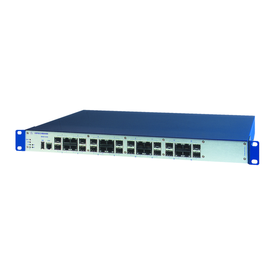
Industrial Ethernet Ruggedized Switch
MACH 1040 Family Full Gigabit
1
MAR1040
FAULT
USB
V.24
RM
Sb
R1
R2
P
2
MAR1040
1
MAR1040
FAULT
USB
V.24
RM
Sb
R1
R2
P
2
MAR1042
1
MAR1140
FAULT
USB
V.24
RM
Sb
R1
R2
P
2
MAR1140
1
MAR1142
FAULT
USB
V.24
RM
Sb
R1
R2
P
2
MAR1142
MAR1140, MAR1142
MACH 1040
Release 02 03/2013
3
5
7
4
6
8
P
3
5
7
4
6
8
3
5
7
4
6
8
P
3
5
7
4
6
8
9
11
13
10
12
14
9
11
13
10
12
14
9
11
13
10
12
14
9
11
13
10
12
14
P
RM Stand by
1
3
5
R1 R2
FAULT
2
4
6
https://hirschmann-support.belden.eu.com
15
16
15
16
U:24/48VDC
I:x.x/x.x A
Relay
15
X
P2
-
+
R2
U:110/230VAC 50HZ/60HZ I:x.x/x.x A
Relay
U:110/250VDC
I:x.x/x.x A
X
P1
-/N
+/L
R1
16
U:24/48VDC
I:x.x/x.x A
Relay
15
P2
X
-
+
R2
U:110/230VAC 50HZ/60HZ I:x.x/x.x A
U:110/250VDC
I:x.x/x.x A
Relay
X
P1
-/N
+/L
R1
16
7
9
11
13
15
8
10
12
14
16
ETHERNET Service Port
Technical support
Advertisement
Table of Contents

Subscribe to Our Youtube Channel
Related Manuals for Belden HIRSCHMANN MACH 1040 Series


Summary of Contents for Belden HIRSCHMANN MACH 1040 Series
- Page 1 Relay U:110/250VDC I:x.x/x.x A MAR1140 U:24/48VDC I:x.x/x.x A Relay MAR1142 FAULT V.24 U:110/230VAC 50HZ/60HZ I:x.x/x.x A U:110/250VDC I:x.x/x.x A Relay MAR1142 RM Stand by R1 R2 FAULT ETHERNET Service Port MAR1140, MAR1142 MACH 1040 Technical support Release 02 03/2013 https://hirschmann-support.belden.eu.com...
- Page 2 The naming of copyrighted trademarks in this manual, even when not specially indicated, should not be taken to mean that these names may be considered as free in the sense of the trademark and tradename protection law and hence that they may be freely used by anyone. ©...
-
Page 3: Table Of Contents
Contents Safety instructions About this Manual Legend Device description General device description Description of the device variants 1.2.1 MAR1040-... with 16 Gigabit ports 1.2.2 MAR1042-... with 16 Gigabit ports and PoE 1.2.3 MAR1040-... with 16 Gigabit ports, ports on back 1.2.4 MAR1142-... -
Page 4: Safety Instructions
Safety instructions Certified usage The device may only be employed for the purposes described in the catalog and technical description, and only in conjunction with external devices and components recommended or approved by the manufacturer. The product can only be operated cor- rectly and safely if it is transported, stored, installed and assembled pro- perly and correctly. - Page 5 Supply with DC voltage: the wire diameter for the input supply line is at least 1 mm² (North America: AWG16). The cross-section of the protective conductor cable is the same size as or bigger than the cross-section of the voltage supply cables.
- Page 6 Housing WARNING ELECTRIC SHOCK Never insert any pointed objects (small screwdrivers, wires, etc.) into the product! Never insert sharp objects (small screwdrivers, wires, etc.) into the connection terminals for the supply voltage or the signal contact, and do not touch the terminals! Only install this device in a switch cabinet or in an operating site with limited access, to which only maintenance staff have access.
- Page 7 Environment The device may only be operated at the specified surrounding air temperature (temperature of the surrounding air at a distance of up to 5 cm (1.97 in) from the device) and relative air humidity specified in the technical data. ...
- Page 8 For use in Hazardous Locations according ISA12.12.01-2007 Class I Div. 2 Groups A, B, C, D Control Drawing MACH1040-Family Hazardous Location Power Supply 1 Signal Contacts ACA21-USB V.24 Interface Data Auto (External communication L: 24VDC to 48VDC (On: O.K. Configuration management) Ethernet Ports M: 100VAC to...
- Page 9 Qualification requirements for personnel Qualified personnel as understood in this manual and the warning signs, are persons who are familiar with the setup, assembly, startup, and operation of this product and are appropriately qualified for their job. This includes, for example, those persons who have been: ...
- Page 10 National and international safety regulations Make sure that the electrical installation meets local or nationally applicable safety regulations. CE marking The devices comply with the regulations contained in the following European directive(s): 2004/108/EC Directive of the European Parliament and the council for standardizing the regulations of member states with regard to electromagnetic compatibility.
- Page 11 FCC note: This device complies with part 15 of FCC rules. Operation is subject to the following two conditions : (1) This device may not cause harmful interference; (2) this device must accept any interference received, including interference that may cause undesired operation. Appropriate testing has established that this device fulfills the requirements of a class A digital device in line with part 15 of the FCC regulations.
-
Page 12: About This Manual
About this Manual The “Installation” user manual contains a device description, safety instructions, a description of the display, and the other information that you need to install the device. The following manuals are available as PDF files on the CD-ROM supplied: ... -
Page 13: Device Description
Device description General device description The MACH 1040 family provides you with a range of device variants. You can set up your device individually based on different criteria: Media type Temperature range Voltage range Software variant The MACH 1040 devices are designed for the special requirements of industrial automation. -
Page 14: Description Of The Device Variants
management software (e.g. Industrial HiVision) a V.24 interface (locally on the Switch) The devices provide you with a large range of functions, which the manuals for the operating software inform you about. These manuals are available as PDF files on the CD ROM provided, or you can download them from the Internet on the Hirschmann product pages (www.hirschmann.com). -
Page 15: Mar1040
1.2.1 MAR1040-... with 16 Gigabit ports MAR1040 FAULT V.24 R1/R2 - Relay: U: 110 / 230 V AC 50HZ / 60HZ I: x.xx / x.xx A U: 24 / 48 V DC I: x.x / x.x A U:110/230VAC 50HZ/60HZ I:x.x/x.x A 2A @ 30V DC (U : 90 - 265 V AC) (U : 18 - 60 V DC) -
Page 16: Mar1042
1.2.2 MAR1042-... with 16 Gigabit ports and PoE MAR1042 FAULT V.24 R1/R2 - Relay: U: 110 / 230 V AC 50HZ / 60HZ I: x.xx / x.xx A U: 24 / 48 V DC I: x.x / x.x A U:110/230VAC 50HZ/60HZ I:x.x/x.x A 2A @ 30V DC (U : 90 - 265 V AC) (U : 18 - 60 V DC) -
Page 17: Mar1040
1.2.3 MAR1040-... with 16 Gigabit ports, ports on back RM Stand by R1 R2 FAULT ETHERNET Service Port U:24/48VDC I:x.x/x.x A Relay MAR1140 FAULT V.24 U:110/230VAC 50HZ/60HZ I:x.x/x.x A U:110/250VDC I:x.x/x.x A Relay FAULT FAULT MAR1140 FAULT V.24 U:110/230VAC 50HZ/60HZ I:x.x/x.x A U:110/250VDC I:x.x/x.x A Relay... -
Page 18: Mar1142
1.2.4 MAR1142-... with 16 Gigabit ports, ports on back and PoE RM Stand by R1 R2 FAULT ETHERNET Service Port U:24/48VDC I:x.x/x.x A Relay MAR1140 FAULT V.24 U:110/230VAC 50HZ/60HZ I:x.x/x.x A U:110/250VDC I:x.x/x.x A Relay FAULT FAULT MAR1140 FAULT V.24 U:110/230VAC 50HZ/60HZ I:x.x/x.x A U:110/250VDC I:x.x/x.x A... -
Page 19: Poe Ports
The device variants of the MACH 1040 with ports on the rear panel have the following characteristics: The display LEDs are on the front of the device. There are 16 LEDs for displaying the status of the Gigabit Ethernet ports and 6 LEDs for displaying the device status. -
Page 20: Signal Contact
The SFP modules are plugged into the SFP slots of the MACH 1040 device in order to obtain an F/O port. The MACH 1040 has 16 TP interfaces and 16 slots for inserting SFP modules (100/1000 Mbit/s). By inserting the SFP module you deactivate the corresponding TP interface. - Page 21 Item Characteristic Ident. Property 1 to 7 Product MAR1040 MACH Ruggedized Gigabit Ethernet Switch MAR1042 MACH Ruggedized Gigabit Ethernet Switch with PoE MAR1140 MACH Ruggedized Gigabit Ethernet Switch, ports on the back MAR1142 MACH Ruggedized Gigabit Ethernet Switch, ports on the back and with PoE - (hyphen) 9 to 10 10/100/1000 Mbit/s ports...
- Page 22 Example of MACH 1040 product designation MACH Ruggedized Switch with 16 Gigabit Ethernet ports 10/100/1000 Mbit/s ports 1 to 4: 4 * Gigabit Ethernet combo ports 10/100/1000 Mbit/s ports 5 to 8: 4 * Gigabit Ethernet combo ports 10/100/1000 Mbit/s ports 9 to 12: 4 * Gigabit Ethernet combo ports 10/100/1000 Mbit/s ports 13 to 16: 4 * Gigabit Ethernet combo ports...
-
Page 23: Assembly And Start-Up
Assembly and start-up The devices have been developed for practical application in a harsh industrial environment. On delivery, the device is ready for operation. The following procedure has been proven to be successful for the assembly of the device: Unpacking and checking ... -
Page 24: Connecting The Power Unit Connections For Supply Voltage And Signal Contact
2.1.3 Connecting the power unit connections for supply voltage and signal contact The voltage supply is connected via a 3-pin terminal block with screw locking. The signal contact is connected via a 2-pin terminal block with screw locking (1 or 2 locks, depending on the device design). Note: For device variants without PoE: The supply voltage in MACH1040/MACH1140 device types can be connected redundantly with two power units. - Page 25 Connecting the supply voltage WARNING ELECTRIC SHOCK Only connect a supply voltage that corresponds to the type plate of your device. Never insert sharp objects (small screwdrivers, wires, etc.) into the connection terminals for the supply voltage, and do not touch the terminals! Failure to follow these instructions can result in death, serious injury, or equipment damage.
- Page 26 Relay Relay -/N +/L -/N +/L Figure 8: Power supply unit “M” (see page 41 „General technical data“): AC voltage (pictured on right) or DC voltage (pictured on left) Connecting 1 - Supply voltage 2 - Signal contact Connection Type “L” Type “M”...
- Page 27 Connecting the signal contact WARNING ELECTRIC SHOCK Never insert sharp objects (small screwdrivers, wires, etc.) into the connection terminals for the signal lines, and do not touch the terminals! Failure to follow these instructions can result in death, serious injury, or equipment damage.
-
Page 28: Installing The Device
2.1.4 Installing the device WARNING ELECTRIC SHOCK Only install this device in a switch cabinet or in an operating site with limited access, to which only maintenance staff have access. Failure to follow these instructions can result in death, serious injury, or equipment damage. - Page 29 The devices are designed to be mounted in a 19" rack. Make sure there is sufficient ventilation. If necessary, provide a fan for the 19" rack. This will prevent the basic devices from overheating. Measure the depth of the 19" cabinet so that all the lines to be connected can be fed in easily.
- Page 30 Y LED LS/D A 6.1 Figure 10: Installation in the switch cabinet with sliding/mounting rails 1 - MACH 1040 device 2 - Sliding/mounting rail 3 - 19" cabinet On delivery, two brackets are attached to the sides of the device (see figure below).
- Page 31 Use the pre-mounted brackets included in the delivery as shown in the following figure (see fig. 13). Attach two additional brackets to the device (see on page 48 „Accessories“, not included in the delivery) as shown in the following figure (see fig.
-
Page 32: Startup Procedure
Figure 13: Vertical mounting on the wall 2.1.5 Startup procedure When you connect the supply voltage, you start up the device. 2.1.6 Connecting the data lines You can connect terminal devices and other segments at the ports of the device via twisted pair cables or F/O cables. ... - Page 33 Autocrossing (if autonegotiation is activated) 1000 Mbit/s full duplex 100 Mbit/s half-duplex mode, 100 Mbit/s full duplex mode 10 Mbit/s half-duplex mode, 10 Mbit/s full duplex mode Also for MAR1042 and MAR1142: Power over Ethernet (PoE, at the first four ports of the device) The PoE voltage is input via the wire pairs transmitting the signal (phantom voltage).
-
Page 34: Display Elements
Note: Make sure that the LH ports are only connected with LH ports, SM ports are only connected with SM ports, and MM ports only with MM ports. 1 Gbit/s fiber optic connection 1 GBit/s fiber optic ports (SFP slot) enable the connection of terminal devices or independent network segments in compliance with the IEEE 802.3-2000 (ISO/IEC 8802-3:2000) 1000BASE-SX or 1000BASE-LX standards. - Page 35 RM Stand by R1 R2 FAULT ETHERNET Service Port U:24/48VDC I:x.x/x.x A Relay MAR1140 FAULT V.24 U:110/230VAC 50HZ/60HZ I:x.x/x.x A Relay U:110/250VDC I:x.x/x.x A Figure 15: Display elements for MAR1140 and MAR1142 Front of device: 1 - Device status display elements 2 - Port status display elements for 16 Gigabit Ethernet ports 3 - Diagnosis port with display element Back of device:...
- Page 36 The following table applies to all device variants: Display Color Activity Meaning Stand- Stand-by None Stand-by mode not enabled by/Sb mode Green Lights up Standby mode enabled Ring None The RM function is deactivated. Manager Green Lights up The RM function is active. The redundant port is disabled.
-
Page 37: Basic Set-Up
Applies to software release 06.0.00 and higher: Display Activity Color Meaning Signal contact 1 Lights up Green The signal contact is open in non manual operation. Yellow The signal contact is open in manual operation. None The signal contact is closed. Signal contact 2 Lights up Green... - Page 38 Configuration via BOOTP Configuration via DHCP (Option 82) AutoConfiguration Adapter Further information on the basic settings of the device can be found in the “Basic Configuration” user manual on the CD ROM. Default settings IP address: The device looks for the IP address using DHCP ...
-
Page 39: Maintenance
VT 100 terminal settings Speed 9,600 Baud Data 8 bit Stopbit 1 bit Handshake Parity none The socket housing is electrically connected to the front panel of the device. The V.24 interface is not electrically isolated from the supply voltage. RJ11 RJ11 n.c. -
Page 40: Disassembling The Device
Disassembling the device To detach the device from the switch cabinet or the wall, remove the screws from the brackets on the device. MAR1040 FAULT V.24 MACH 1040 Release 02 03/2013... -
Page 41: Technical Data
Technical data General technical data Dimensions MAR1... 448 x 44 x 345 mm W x D x H (without brackets) Weight MAR1040..., MAR1140... max. 4.2 kg MAR1040..., MAR1140... max. 4.4 kg Devices with redundant power unit MAR1042..., MAR1142... max. 4.6 kg Devices with PoE power unit Power supply Nominal voltage range AC... - Page 42 Pollution degree Protection classes Laser protection Class 1 according to EN 60825-1 (2007) Protection class IP 30 a. If you use SFP modules without the supplement „EEC“ then the operating temperature range of the device is 0 °C to 55 °C (see page 48 „Accessories“.) MACH 1040 Release 02 03/2013...
- Page 43 EMC and immunity EMC interference Description Test level immunity IEC/EN 61850- 3:2002 EMI TYPE tests, test in comp. with IEC/EN 61000-4-2 Electrostatic discharge Contact discharge ± 8 kV Air discharge ± 15 kV IEC/EN 61000-4-3 Electromagnetic field 80 MHz ... 2700 MHz 20 V/m IEC/EN 61000-4-4 Fast transients (burst)
- Page 44 EMC interference Description Test level immunity IEEE 1613:2009 EMI TYPE tests, test in comp. with IEEE C37.90.1 Fast transients (burst) DC Power Line ± 4 kV AC Power Line ± 4 kV Data line ± 4 kV IEEE C37.90.1 damped oscillation DC Power Line ±...
- Page 45 Network range Note: The line lengths specified for the transceivers apply for the respective fiber data (fiber attenuation and BLP/dispersion). TP port Length of a twisted pair segment max. 100 m / 328 ft (cat5e cable with 1000BASE-T) Table 6: TP port 10BASE-T / 100BASE-TX / 1000BASE-T Product Wave...
- Page 46 Product Wave Wave Fiber System Example Fiber Dispersion code length length attenuation for F/O attenuation M-SFP- line BIDI... length Type A SM 1310 nm 1550 nm 9/125 µm 0-11 dB 0-20 km 0.4 dB/km 3.5 ps/ LX/LC (nm*km) Type B SM 1550 nm 1310 nm 9/125 µm 0-11 dB 0-20 km 0.25 dB/km 19 ps/ LX/LC...
- Page 47 Power consumption/power output Device variants without PoE (MAR1040..., Maximum Maximum MAR1140...) power consumption power output Device (without SFP modules, without TP links) 10 W 34 Btu (IT)/h additionally for each connected SFP module 3 Btu (IT)/h additionally for each TP port with link 0.8 W 3 Btu (IT)/h Device at full capacity (16 links)
- Page 48 Accessories Note: Please note that products recommended as accessories may have characteristics that do not fully correspond to those of the corresponding product. This may limit their possible usage in the overall system. Gigabit Ethernet SFP transceiver Order number M-SFP-SX/LC 943 014-001 M-SFP-SX/LC EEC...
- Page 49 Underlying norms and standards Name EN 61000-6-2 Generic norm – immunity in industrial environments EN 55022 IT equipment – radio interference characteristics EN 60950-1 Safety for the installation of IT equipment EN 61131-2 Programmable logic controllers EN 50121-4 Railway applications - EMC - emitted interference and interference immunity for signal and telecommunication systems FCC 47 CFR Part 15 Code of Federal Regulations...
-
Page 50: A Further Support
Contact our support at https://hirschmann-support.belden.eu.com You can contact us in the EMEA region at Tel.: +49 (0)1805 14-1538 E-mail: hac.support@belden.com in the America region at Tel.: +1 (717) 217-2270 E-mail: inet-support.us@belden.com in the Asia-Pacific region at ... - Page 51 MACH 1040 Release 02 03/2013...
Need help?
Do you have a question about the HIRSCHMANN MACH 1040 Series and is the answer not in the manual?
Questions and answers