
Subscribe to Our Youtube Channel
Related Manuals for Belden Hirschman RSPS20


Summary of Contents for Belden Hirschman RSPS20
- Page 1 User Manual Installation Industrial Ethernet Rail Switch Power Smart RSPS20/25 Installation RSPS20/25 Technical support Release 09 12/2019 https://hirschmann-support.belden.com...
- Page 2 The naming of copyrighted trademarks in this manual, even when not specially indicated, should not be taken to mean that these names may be considered as free in the sense of the trademark and tradename protection law and hence that they may be freely used by anyone. ©...
- Page 3 Contents Safety instructions About this manual Description General description Device name and product code Device views 1.3.1 Front view 1.3.2 Rear view Power supply 1.4.1 Supply voltage with the characteristic value M9 or K9 1.4.2 Supply voltage with the characteristic value CC Ethernet ports 1.5.1 100/1000 Mbit/s twisted pair port (optional) 1.5.2 100 Mbit/s F/O port (optional)
-
Page 4: Table Of Contents
2.5.1 Supply voltage with the characteristic value M9 or K9 2.5.2 Supply voltage with the characteristic value CC 2.5.3 Signal contact Operating the device Connecting data cables Filling out the inscription label Making basic settings Upgrading Software Monitoring the ambient air temperature Maintenance and service Disassembly Removing the device... - Page 5 Safety instructions WARNING UNCONTROLLED MACHINE ACTIONS To avoid uncontrolled machine actions caused by data loss, configure all the data transmission devices individually. Before you start any machine which is controlled via data transmission, be sure to complete the configuration of all data transmission devices. Failure to follow these instructions can result in death, serious injury, or equipment damage.
- Page 6 Device casing Only technicians authorized by the manufacturer are permitted to open the casing. Never insert pointed objects (narrow screwdrivers, wires, etc.) into the device or into the connection terminals for electric conductors. Do not touch the connection terminals. ...
- Page 7 All of the following requirements are complied with: The electrical wires are voltage-free. The cables used are permitted for the temperature range of the application case. Table 1: Requirements for connecting electrical wires Requirements for connecting the signal contact ...
- Page 8 Device variant Requirements Only for device If you connect 2 independent power sources, verify that the minus variants featuring terminal is grounded. Failure to follow this instruction can result in supply voltage with equipment damage. the characteristic value CC: The wire diameter of the power supply cable is at least 1 mm² (North America: AWG16) on the supply voltage input.
- Page 9 CE marking The labeled devices comply with the regulations contained in the following European directive(s): Device variant Directive All variants 2014/30/EU (EMC) Directive of the European Parliament and of the Council on the harmonisation of the laws of the Member States relating to electromagnetic compatibility.
- Page 10 Supplier's Declaration of Conformity 47 CFR § 2.1077 Compliance Information RSPS20/25 U.S. Contact Information Belden – St. Louis 1 N. Brentwood Blvd. 15th Floor St. Louis, Missouri 63105, United States Phone: 314.854.8000 This device complies with part 15 of the FCC rules. Operation is subject to the following two conditions: (1) this device may not cause harmful interference;...
- Page 11 About this manual The “Installation” user manual contains a device description, safety instructions, a description of the display, and the other information that you need to install the device. Documentation mentioned in the “User Manual Installation” that is not supplied with your device as a printout can be found as PDF files for downloading on the Internet at: https://www.doc.hirschmann.com Installation RSPS20/25...
- Page 12 The symbols used in this manual have the following meanings: Listing Work step Subheading Installation RSPS20/25 Release 09 12/2019...
- Page 13 Description General description The RSPS20/25 devices are designed for the special requirements of industrial automation. They meet the relevant industry standards, provide very high operational reliability, even under extreme conditions, and also long-term reliability and flexibility. You can choose from between a wide range of variants. You have the option to set up your device individually based on different criteria: ...
- Page 14 The characteristic values stand for specific product properties. You have numerous options of combining the device characteristics. You can determine the possible combinations using the Configurator which is available in the Belden Online Catalog https://catalog.belden.com on the web page of the device.
- Page 15 Item Characteristic Character Description istic value 19 ... 20 Supply voltage 2 voltage inputs for redundant power supply Rated voltage range DC: 24 V DC ... 48 V DC 1 voltage input Rated voltage range AC: 110 V AC ... 230 V AC, 50 Hz ... 60 Hz Rated voltage range DC: 60 V DC ...
- Page 16 Application case Certificates and declarations Characteristic value Standard applications EN 60950-1 EN 61131-2 UL 508 UL 60950-1 Substation applications IEC 61850-3 IEEE 1613 Oil and gas applications ISA-12.12.01 – Class I, Div. 2 Railway applications (trackside) EN 50121-4 Navy applications Table 5: Assignment: application cases, certificates and declarations, characteristic values a.
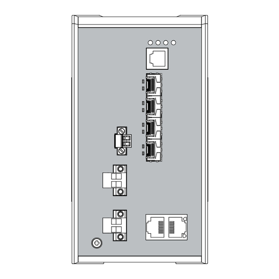
- Page 17 Device views 1.3.1 Front view Front view: on the left: Device variants RSPS...2Z6YT..CC..on the right: Device variants RSPS...2Z6TT..M9/K9..LED display elements for device status V.24 interface Uplink ports 2 × SFP slot for 100 Mbit/s F/O connections Other ports alternatively, Port configuration 2 ×...
- Page 18 Supply voltage connection alternatively, Supply voltage with 2 voltage inputs for redundant power supply depending on the characteristic 2-pin terminal block device variant value: Supply voltage with 1 voltage input the characteristic 3-pin terminal block value: M9 or K9 Connection for the signal contact Front view of device variants RSPS...2T1TT..
- Page 19 Supply voltage connection alternatively, Supply voltage with 2 voltage inputs for redundant power supply depending on the characteristic 2-pin terminal block device variant value: Supply voltage with 1 voltage input the characteristic 3-pin terminal block value: M9 or K9 Connection for the signal contact 1.3.2...
-
Page 20: Supply Voltage With The Characteristic Value M9 Or K9
Power supply You will find information on the characteristic values here: “Device name and product code” on page 14 1.4.1 Supply voltage with the characteristic value M9 or K9 The following options for power supply are available: 1 × 3-pin terminal block You will find information on connecting the supply voltage here: See “Supply voltage with the characteristic value M9 or K9”... - Page 21 1.5.2 100 Mbit/s F/O port (optional) This port is an SFP slot. The 100 Mbit/s F/O port allows you to connect network components according to the IEEE 802.3 100BASE-FX standard. This port supports: 100 Mbit/s half-duplex mode, 100 Mbit/s full duplex mode Default setting: Full duplex Display elements After the supply voltage is set up, the Software starts and initializes the...
- Page 22 Display Color Activity Meaning Ring Manager — none No redundancy configured green lights up Redundancy exists flashes 1 time Device is reporting an incorrect a period configuration of the RM function yellow lights up No redundancy exists Storage medium — none ACA storage medium not connected ACA31...
- Page 23 Management interfaces 1.7.1 V.24 interface (external management) A serial interface is provided on the RJ11 socket (V.24 interface) for the local connection of an external management station (VT100 terminal or PC with corresponding terminal emulation). This enables you to set up a connection to the Command Line Interface CLI and to the System Monitor.
- Page 24 Signal contact Figure 2: Signal contact: 2-pin terminal block with screw locking The signal contact is a potential-free relay contact. The signal contact is open when the device is not connected to a power supply. The signal contact allows you to control external devices or monitor device functions.
- Page 25 Installation The devices have been developed for practical application in a harsh industrial environment. On delivery, the device is ready for operation. Perform the following steps to install and configure the device: Checking the package contents Installing the SD card (optional) ...
- Page 26 Installing and grounding the device WARNING FIRE HAZARD Install the device in a fire enclosure according to EN 60950-1. Failure to follow this instruction can result in death, serious injury, or equipment damage. Exclusively for device variants featuring supply voltage with characteristic value K9 or M9: WARNING ELECTRIC SHOCK...
- Page 27 Note: The overall shield of a connected shielded twisted pair cable is connected to the grounding connector on the front panel as a conductor. 2.3.2 Grounding the device The housing is grounded via the separate ground screw on the bottom left of the front side of the device.
- Page 28 Installing an SFP transceiver (optional) Prerequisites: Exclusively use Hirschmann SFP transceivers. See “Accessories” on page 48. Figure 3: Installing SFP transceivers: Installation sequence Proceed as follows: Take the SFP transceiver out of the transport packaging (1). Remove the protection cap from the SFP transceiver (2). ...
- Page 29 2.5.1 Supply voltage with the characteristic value M9 or K9 You will find information on the characteristic values here: “Device name and product code” on page 14 Figure 4: Supply voltage with the characteristic value M9 or K9: 3-pin terminal block with screw locking Type of the voltages Specification of the supply...
-
Page 30: Supply Voltage With The Characteristic Value Cc
WARNING ELECTRIC SHOCK Install this device solely in a switch cabinet or in an operating site with restricted access, to which maintenance staff have exclusive access. Failure to follow this instruction can result in death, serious injury, or equipment damage. For the supply voltage to be connected, perform the following steps: ... -
Page 31: Signal Contact
For every supply voltage to be connected, perform the following steps: Remove the terminal connector from the device. Connect the wires according to the pin assignment on the device with the clamps. Fasten the wires in the terminal block by tightening the terminal screws. ... -
Page 32: Operating The Device
Operating the device Relevant for North America: You find the prescribed tightening torque in chapter: “General technical data” on page 39 Proceed as follows: Use screws to secure the connectors to the device. Enable the supply voltage. Connecting data cables Note the following general recommendations for data cable connections in environments with high electrical interference levels: ... -
Page 33: Making Basic Settings
Making basic settings The IP parameters must be entered when the device is installed for the first time. The device provides the following options for configuring IP addresses: Input via the V.24 interface Input via the HiView or HiVision application. You find further information about the applications HiView or HiVision on the Internet at the Hirschmann product pages: HiView... -
Page 34: Upgrading Software
Upgrading Software For RSPS20/25 devices, you have the option of performing upgrades with the software level 2S. For software version 04.0 or higher, the software image “HiOS” is available for this purpose. Installation RSPS20/25 Release 09 12/2019... -
Page 35: Monitoring The Ambient Air Temperature
Monitoring the ambient air temperature Operate the device below the specified maximum ambient air temperature exclusively. See “General technical data” on page 39. The ambient air temperature is the temperature of the air at a distance of 2 in (5 cm) from the device. It depends on the installation conditions of the device, for example the distance from other devices or other objects, and the output of neighboring devices. -
Page 36: Maintenance And Service
Maintenance and service When designing this device, Hirschmann largely avoided using high-wear parts. The parts subject to wear and tear are dimensioned to last longer than the lifetime of the product when it is operated normally. Operate this device according to the specifications. ... -
Page 37: Disassembly
Disassembly Removing the device WARNING ELECTRIC SHOCK Disconnect the grounding only after disconnecting all other cables. Failure to follow this instruction can result in death, serious injury, or equipment damage. Proceed as follows: Disconnect the data cables. Disable the supply voltage. ... -
Page 38: Removing An Sfp Transceiver (Optional)
Removing an SFP transceiver (optional) Figure 6: De-installing SFP transceivers: De-installation sequence Proceed as follows: Open the locking mechanism of the SFP transceiver (1). Pull the SFP transceiver out of the slot via the open locking mechanism (2). ... -
Page 39: Technical Data
Technical data General technical data Dimensions RSPS20/25 See “Dimension drawings” on page 42. W × H × D Weight RSPS20-... approx. 2.42 lb (1.1 kg) RSPS25-..-S..approx. 2.42 lb (1.1 kg) RSPS25-..-T/E..approx. 2.65 lb (1.2 kg) Supply voltage Rated voltage DC: 24 V DC ... - Page 40 Supply voltage Rated voltage AC: 110 V AC ... 230 V AC, 50 Hz ... 60 Hz with the Voltage range AC incl. maximum 88 V AC ... 265 V AC, 47 Hz ... 63 Hz characteristic tolerances: value K9 Rated voltage DC: 60 V DC ...
- Page 41 Signal contact Connection type 2-pin terminal block Tightening torque 3 lb-in (0.34 Nm) Switching current max. 1 A Switching voltage max. 60 V DC max. 30 V AC under UL conditions: max. 30 V DC, resistive load Pollution degree Protection Laser protection Class 1 in compliance with IEC 60825-1 classes...
-
Page 42: Dimension Drawings
Dimension drawings 114,7 6,55 4.52 inch 0.26 2.76 89,9 3.54 Figure 7: Dimensions Installation RSPS20/25 Release 09 12/2019... -
Page 43: Emc And Immunity
EMC and immunity You will find detailed information on the certificates and declarations applying to your device in a separate overview. See table 5 on page 16. Stability Standard Marine Railway Sub-station applications applications applications applications (trackside) IEC 60068-2-6, test Fc Vibration —... - Page 44 EMC interference Standard Marine Railway Sub-station emission applications applications applications applications (trackside) Radiated emission EN 55032 Class A Class A Class A Class A GL Guidelines — EMC 1 — — FCC 47 CFR Part 15 Class A Class A Class A Class A EN 61000-6-4...
- Page 45 EMC interference Standard Marine Railway Sub-station immunity applications applications applications applications (trackside) Fast transients (burst) EN 61000-4-4 AC/DC supply connection ±2 kV ±2 kV ±2 kV ±4 kV IEEE C37.90.1 EN 61000-4-4 Data line ±4 kV ±4 kV ±4 kV ±4 kV IEEE C37.90.1 Voltage surges - DC supply connection...
- Page 46 EMC interference Standard Marine Railway Sub-station immunity applications applications applications applications (trackside) Damped oscillation - AC/DC supply connection EN 61000-4-12 line/ground — — — 2.5 kV IEEE C37.90.1 EN 61000-4-12 line/line — — — 1 kV IEEE C37.90.1 Damped oscillation – data line EN 61000-4-12 line/ground —...
-
Page 47: Network Range
Network range Note: The line lengths specified for the transceivers apply for the respective fiber data (fiber attenuation and Bandwidth Length Product (BLP)/ Dispersion). Product code Mode Wave length Fiber System Example for F/O Fiber attenuation BLP/Dispersion M-FAST-SFP-... attenuation cable length -MM/LC... -
Page 48: Power Consumption/Power Output
Power consumption/power output The order numbers correspond to the product codes of the devices. See “Device name and product code” on page 14. Device name Maximum Power output power consumption RSPS20-..2Z6YT..10 W 34 Btu (IT)/h RSPS20-..2Z6TT..27 Btu (IT)/h RSPS20-..2T1TT.. - Page 49 Name Order number 2-pin terminal block for signal contact (50 pieces) 943 845-010 Power Cord 942 000-001 Network management software HiVision 943 156-xxx Protection cap for RJ45 socket (50 pieces) 943 936-001 Protection cap for SFP slot (25 pieces) 943 942-001 Fast Ethernet SFP transceiver Order number M-FAST SFP-TX/RJ45...
-
Page 50: Underlying Technical Standards
Underlying technical standards Name Bureau Veritas Rules for the Classification of Steel Ships – BV CSA C22.2 No. 142 Canadian National Standard(s) – Process Control Equipment – Industrial Products ANSI/UL 121201 Nonincendive Electrical Equipment for Use in Class I and II, Division 2 and Class III, Divisions 1 and 2 Hazardous (Classified) Locations EN 50121-4... -
Page 51: A Further Support
A list of local telephone numbers and email addresses for technical support directly from Hirschmann is available at https:// hirschmann-support.belden.com. This site also includes a free of charge knowledge base and a software download section. Hirschmann Competence Center The Hirschmann Competence Center is ahead of its competitors on three counts with its complete range of innovative services: ...
Need help?
Do you have a question about the Hirschman RSPS20 and is the answer not in the manual?
Questions and answers