
Related Manuals for Belden HIRSCHMANN OWL 4G


Summary of Contents for Belden HIRSCHMANN OWL 4G
- Page 1 User Manual Installation Industrial Cellular Router OWL 4G North America UM Installation OWL 4G North America Technical support Release 03 - 11/2021 https://hirschmann-support.belden.com...
- Page 2 The naming of copyrighted trademarks in this manual, even when not specially indicated, should not be taken to mean that these names may be considered as free in the sense of the trademark and tradename protection law and hence that they may be freely used by anyone. c 2021 Hirschmann Automation and Control GmbH Manuals and software are protected by copyright.
-
Page 3: Table Of Contents
Contents 1 Safety Instructions 2 FCC note 3 About this Manual 4 Router Description 4.1 Usage of the Router ........15 5 Contents of Package 6 Router Design 6.1 Router Versions... - Page 4 10 Related Documents 11 Further Support UM Installation OWL 4G North America Release 03 - 11/2021...
- Page 5 List of Figures Access to the Internet from LAN ......15 Backed up access to the Internet .
- Page 6 List of Tables Contents of package ........17 Router versions .
- Page 7 Used Symbols Danger – Information regarding user safety. Note – Problems that can arise in specific situations. Information – Useful tips or information of special interest. Example – Example of function, command or script. UM Installation OWL 4G North America Release 03 - 11/2021...
- Page 8 1 Safety Instructions WARNING UNCONTROLLED MACHINE ACTIONS To avoid uncontrolled machine actions caused by data loss, configure all the data transmis- sion devices individually. Before you start any machine which is controlled via data transmission, be sure to complete the configuration of all the data transmission devices. Failure to follow these instructions can result in death, serious injury, or equipment damage.
- Page 9 Installation site requirements When you are selecting the installation location, make sure you observe the climatic threshold values specified in the technical data. Operate the device at the specified ambient temperature (temperature of the ambient air at a distance of 2 in (5 cm)). Use the device in an environment with a maximum pollution degree that complies with the specifications in the technical data.
- Page 10 Install and operate this equipment with a minimum distance of 7.9 in (20 cm) between the antenna and your body. Recycling note After usage, this device must be disposed of properly as electronic waste, in accordance with the current disposal regulations of your county, state, and country. UM Installation OWL 4G North America Release 03 - 11/2021...
- Page 11 Grounding the device The device is grounded via the grounding screw. Shielding ground The shielding ground of the connectable twisted pair cable is connected to the grounding connector as a conductor. Beware of possible short circuits when connecting a cable section with conductive shielding braiding.
- Page 12 Supplier’s Declaration of Conformity 47 CFR § 2.1077 Compliance Information OWL 4G North America U.S. Contact Information Belden – St. Louis 1 N. Brentwood Blvd. 15th Floor St. Louis, Missouri 63105, United States Phone: 314.854.8000 This device complies with part 15 of the FCC rules.
-
Page 13: About This Manual
3 About this Manual The "Instalation" user manual contains a device description, safety instructions, a description of the display, and the other information that you need to install the device. Documentation mentioned in the "User Manual Installation" that is not supplied with your device as a printout can be found as PDF files for downloading on the Internet at: https://www.doc.hirschmann.com/. -
Page 14: Router Description
4 Router Description OWL 4G North America is an industrial cellular router intended for the North American market (NAM). This router is an ideal device for wireless communication in mobile networks that make use of LTE and WCDMA technology. Due to the high speed of data transfer up to 150 Mbps (download) and up to 50 Mbps (upload) is this router an ideal solution for specialized M2M devices and IoT as well as for wireless connection of traffic and security camera systems, individual computers, LAN networks, automatic teller machines (ATM) and other self-service... -
Page 15: Usage Of The Router
4.1 Usage of the Router The router is primarily intended for these four basic situations: I. Access to the Internet from LAN Figure 1: Access to the Internet from LAN II. Backed up access to the Internet (from LAN) Figure 2: Backed up access to the Internet UM Installation OWL 4G North America Release 03 - 11/2021... -
Page 16: Using Vpn Tunnel
III. Secure networks interconnection or using VPN Figure 3: Using VPN tunnel IV. Serial Gateway Figure 4: Serial Gateway UM Installation OWL 4G North America Release 03 - 11/2021... -
Page 17: Contents Of Package
5 Contents of Package The standard set of router includes items listed in the following table: Item# Description Figure Q’ty Router 1 pcs DIN holder 1 pcs (screwed on the router) Wing for wall mounting 2 pcs (screwed on the router) 2-pin terminal block for power supply 1 pcs (deployed on the router) -
Page 18: Router Design
6 Router Design 6.1 Router Versions OWL 4G North America router is supplied in the following versions (see table below). All versions are available in metal box. Router versions Version without WiFi and GNSS Version with WiFi and GNSS Table 2: Router versions Figure 5: Version without WiFi and GNSS Figure 6: Version with WiFi and GNSS UM Installation OWL 4G North America... -
Page 19: Order Codes
6.2 Order codes Order codes overview is shown in the table below. Product type Product name Order code Features – interfaces OWL 4G OWL 4G 942 284-001 LTE module for NAM, 2x ETH, 1x BI, 1x BO, North America 1x RS232, 1x RS485, 2x SIM reader OWL 4G OWL 4G 942 284-101... -
Page 20: Basic Dimensions Of The Router Box (Specified In Mm)
6.3 Basic Dimensions of the Router Box (specified in mm) Figure 7: Basic dimensions of the router box Figure 8: Basic dimensions of the router box UM Installation OWL 4G North America Release 03 - 11/2021... -
Page 21: Mounting Recommendations
6.4 Mounting Recommendations The router can be placed: on a flat surface, on a wall (or another surface) using the side wings, on a DIN rail EN 60715 with the included metal DIN rail clip. If the negative pole of the router is grounded, there is no protection against reversed polarity! The only protection left is the fuse inside the device. -
Page 22: Removing From The Din Rail
6.5 Removing from the DIN Rail The DIN rail clip is suitable for a DIN rail according to EN 60715 standard only. The default position of metal rail clip, which is used for mounting the router on a DIN rail, is shown in the following figure. -
Page 23: Description Of The Front Panel
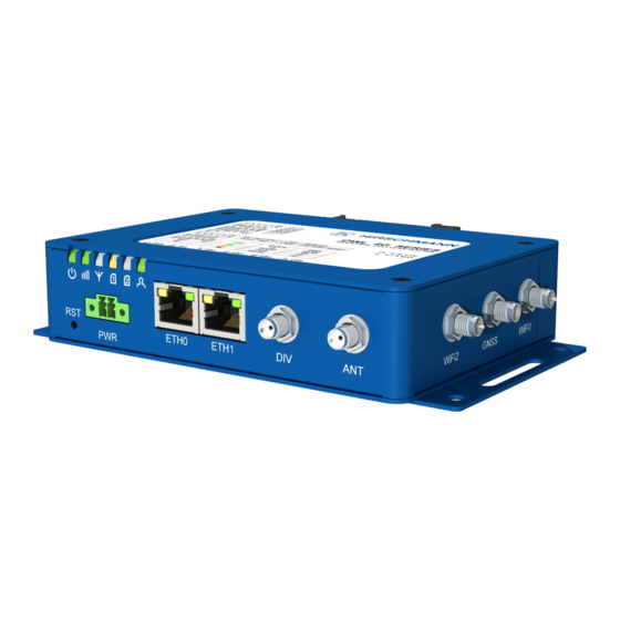
6.6 Description of the Front Panel On the front panel of the router, there are located: Caption Connector Description — RST button used to restore the default configuration and re- boot the router 2-pin Terminal block for the power supply ETH0 RJ45 Ethernet connection to the computer network... -
Page 24: Status Indication
6.6.1 Status Indication There are six LED indicators on the front panel to provide router status information. Each ETH port has two additional LEDs that provide information about the port status. Caption Color State Description Green Starting of the router Green Blinking Router is ready... -
Page 25: Power Connector Pwr
6.6.2 Power Connector PWR Terminal block 3.5 mm. Pin number Signal mark Description VCC(+) Positive pole of DC supply voltage (+9 to +36 V DC) GND(-) Negative pole of DC supply voltage Table 6: Connection of power connector Figure 12: Power connector Power supply for router is required between +9 V to +36 V DC supply. -
Page 26: Ethernet Port Eth0 And Eth1
6.6.3 Ethernet Port ETH0 and ETH1 The panel socket of RJ45 is used for this interface. The insulation strength of Ethernet ports from each other and from the rest of the router (grounding) is 1500 V. Signal mark Description Data flow direction TXD+ Transmit Data –... -
Page 27: Ant, Div, Gnss And Wifi Antenna Connectors
6.6.4 ANT, DIV, GNSS and WiFi Antenna Connectors The main and diversity antennas are connected to the router using the SMA connectors on the front panel. For the WiFi version, there are also two R-SMA connectors for connection of the WiFi antennas and one SMA connector for connection of the GNSS antenna on the right panel of the router. -
Page 28: Reset Button
6.6.5 Reset Button The RST button on the front panel has three functions on OWL 4G routers: Reboot the router: Hold the RST button for less than 4 seconds, the router will be restarted. Factory reset – restore the default configuration: Hold the RST button for more than 4 seconds. -
Page 29: Overview Of Router Reboot And Reset
Action Router behavior Trigger events – options Reboot Turns off and then turns on the router Disconnect and reconnect the power Send text reboot via SMS to SIM card number put in your router (your phone number has to be authorized –... -
Page 30: Description Of The Left Panel
6.7 Description of the Left Panel Interfaces located on the left panel are described in the table below. Caption Connector Description Grounding screw M3 screw Grounding screw (M3x6L) is connected to the ground of the board and to the negative pole of the power source. SIM cards 2FF size Unscrew the SIM cards cover to access the SIM1 and... -
Page 31: Sim Card Reader
6.7.1 SIM Card Reader Two SIM card readers for 3 V and 1.8 V SIM cards are located on the left panel of the router. In order for the router to function, it is necessary to insert an activated SIM card with an unblocked PIN code, or you can enter the PIN code in the router web interface. -
Page 32: Serial Interfaces And I/O Port
6.7.2 Serial Interfaces and I/O Port The RS232 and RS485 serial interfaces together with the I/O interface are physically con- nected to the 10-pin panel socket. All three interfaces are not isolated from the router. The pinout of this conector is described in the tables below. Figure 20: Serial + I/O connector Signal mark Description... -
Page 33: Functional Scheme Of The Binary Interface
The functional scheme of connection for the binary input and binary output is drawn on the picture below. Figure 21: Functional scheme of the binary interface UM Installation OWL 4G North America Release 03 - 11/2021... -
Page 34: Description Of The Right Panel
6.8 Description of the Right Panel Connectors located on the right panel are described in the table below. This panel has no connectors on it for the non-WiFi version of the router. Caption Connector Description WiFi2 R-SMA Connector for the second WiFi antenna. GNSS Connector for the GNSS receiver antenna. -
Page 35: First Use
7 First Use 7.1 Connecting the Router Before First Use Before putting the router into operation it is necessary to connect all of the components that are required to run your applications. Don’t forget to insert a SIM card. The router can not operate without a connected antenna, SIM card and power supply. If the antenna is not connected, the router may be damaged. - Page 36 Applies to devices that are delivered with an unique default password that is located on a label on the device Perform the following steps: 1. Open the web interface the first time you log on to the device. 2. Type in the user name “admin”. 3.
-
Page 37: Maintenance And Service
8 Maintenance and Service When designing this device, Hirschmann largely avoided using high-wear parts. The parts subject to wear and tear are dimensioned to last longer than the lifetime of the product when it is operated normally. Operate this device according to the specifications. Relays are subject to natural wear. -
Page 38: Technical Parameters
9 Technical Parameters 9.1 Basic Parameters Router parameters Temperature range Operating -40 C to +65 C Storage -40 C to +85 C Humidity Operating 0 to 95 % relative humidity non condensing Storage 0 to 95 % relative humidity non condensing Altitude Operating 2000 m / 70 kPa... -
Page 39: Standards And Regulations
9.2 Standards and Regulations The router complies with the following standards and regulations: Standards and regulations Radio PTCRB FCC 15.107 Class B, FCC 15.109 Class B, IC Safety UL/EN/AS/NZS 62368-1 Carrier approvals AT&T, Verizon, FirstNet Transportation E-Mark E8 homologation number: 10R – 05 10350, EN 45545-2 Railway EN 50155 (A1, OT4, ST1, H1, Cat 1 Class B, S1, C1, L4, PD2,... -
Page 40: Type Tests And Environmental Conditions
9.3 Type Tests and Environmental Conditions Phenomena Test Description Test levels EN 61000-4-2 Enclosure contact 6 kV (crit. A) Enclosure air 8 kV (crit. A) RF field AM EN 61000-4-3 Enclosure 20 V/m (crit. A) modulated (80 – 1000 MHz) 10 V/m (crit. -
Page 41: Technical Parameters Of Cellular Module
9.4 Technical Parameters of Cellular Module Technical parameters of cellular module LTE parameters LTE: Cat.4, 3GPP E-UTRA Release 11 LTE technology FDD frequencies: B71 (600 MHz), B12, B13, B14 (700 MHz), B5 (850 MHz), B4, B66 (1700 MHz), B2 (1900 MHz) LTE FDD bit rates: 150 Mbps (DL) / 50 Mbps (UL) Supported bandwidths: 1.4 MHz, 3 MHz, 5 MHz, 10 MHz, 15 MHz, 20 MHz... -
Page 42: Technical Parameters Of Gnss
9.6 Technical Parameters of GNSS GNSS specifications Antenna – active Protocols NMEA 0183 GNSS Systems GPS, GLONASS, BeiDou, Galileo, QZSS Frequency GPS/Galileo/QZSS: 1575.42 1.023 MHz GLONASS: 1597.5 – 1605.8 MHz BeiDou: 1561.1 2.046 MHz Sensitivity (autonomous) Tracking: -157 dBm Reacquisition: -157 dBm Cold start: -146 dBm Acquisition time Hot start: 2.5 s... - Page 43 10 Related Documents The “Configuration” user manual, Application Notes, and documentation of several OWL user modules can be found as PDF files for downloading on the Internet at: https://www.doc.hirschmann.com/. UM Installation OWL 4G North America Release 03 - 11/2021...
- Page 44 You find the addresses of our partners on the Internet at http://www.hirschmann.com. A list of local telephone numbers and email addresses for technical support directly from Hirschmann is available at https://hirschmann-support.belden.com. This site also includes a free of charge knowledge base and a software download section.
Need help?
Do you have a question about the HIRSCHMANN OWL 4G and is the answer not in the manual?
Questions and answers