Table of Contents
Advertisement
Quick Links
S19A/S24A-QM87i Marine Panel PC
MODEL:
S19A/S24A-QM87i
Marine Panel PC with Intel® Core™ i5-4400E
Dual-Core CPU, Intel® QM87 Express Chipset, GbE LAN,
Four Isolated RS-232/422/485, CAN Bus, HDMI, DVI-D, VGA,
CFast Slot, USB 2.0, USB 3.0, iRIS-2400, RoHS Compliant
User Manual
Page I
Rev. 1.02 – February 21, 2018
Advertisement
Chapters
Table of Contents

Subscribe to Our Youtube Channel
Related Manuals for IEI Technology S19A/S24A-QM87i


Summary of Contents for IEI Technology S19A/S24A-QM87i
- Page 1 S19A/S24A-QM87i Marine Panel PC MODEL: S19A/S24A-QM87i Marine Panel PC with Intel® Core™ i5-4400E Dual-Core CPU, Intel® QM87 Express Chipset, GbE LAN, Four Isolated RS-232/422/485, CAN Bus, HDMI, DVI-D, VGA, CFast Slot, USB 2.0, USB 3.0, iRIS-2400, RoHS Compliant User Manual Page I Rev.
- Page 2 S19A/S24A-QM87i Marine Panel PC Revision Date Version Changes February 21, 2018 1.02 Added some notes December 12, 2017 1.01 Eliminate “i5” from the model name to make it consistent with other panel PC models July 8, 2015 1.00 Initial release...
- Page 3 S19A/S24A-QM87i Marine Panel PC Copyright COPYRIGHT NOTICE The information in this document is subject to change without prior notice in order to improve reliability, design and function and does not represent a commitment on the part of the manufacturer. In no event will the manufacturer be liable for direct, indirect, special, incidental, or consequential damages arising out of the use or inability to use the product or documentation, even if advised of the possibility of such damages.
-
Page 4: Table Of Contents
S19A/S24A-QM87i Marine Panel PC Table of Contents 1 INTRODUCTION ......................1 1.1 O ........................2 VERVIEW 1.2 F ........................2 EATURES 1.3 F ......................3 RONT ANEL 1.3.1 Display Control Buttons ..................4 1.4 T ......................... 4 ANEL 1.5 B ...................... - Page 5 S19A/S24A-QM87i Marine Panel PC 3.8 P ..................35 OWERING N THE YSTEM 3.9 C CMOS ......................36 LEAR 3.10 D ................... 37 RIVER NSTALLATION 3.11 IPMI S ..................38 ETUP ROCEDURE 3.11.1 Managed System Hardware Setup ..............38 3.11.2 Using the IEI iMAN Web GUI ................ 38 4 ON-SCREEN-DISPLAY (OSD) C ONTROLS ............
- Page 6 S19A/S24A-QM87i Marine Panel PC 5.3.12 IEI Feature ..................... 71 5.4 C ........................72 HIPSET 5.4.1 PCH-IO Configuration ..................72 5.4.2 System Agent (SA) Configuration ..............74 5.4.2.1 Graphics Configuration ................75 5.4.3 Memory Configuration ..................77 5.5 B ........................77 5.6 S...
- Page 7 S19A/S24A-QM87i Marine Panel PC 7.2.16 SATA Connector (S_ATA2) ................99 7.2.17 SATA Power Connector (SATA_PWR1) ............99 7.2.18 SATA Power Connector (SATA_PWR2) ............100 7.2.19 SMBus Connector, EC (SMB1) ..............100 7.2.20 SPI Flash Connector (SPI1) ................ 100 7.2.21 SPI Flash Connector, EC (CN2) ..............101 7.2.22 TPM Connector (TPM1) ................
- Page 8 S19A/S24A-QM87i Marine Panel PC List of Figures Figure 1-1: S19A-QM87i Marine Panel PC ..................2 Figure 1-2: S24A-QM87i Front Panel .................... 3 Figure 1-3: Display Control Buttons ..................... 4 Figure 1-4: Top Panel ........................4 Figure 1-5: Bottom Panel ....................... 6 Figure 1-6: S19A-QM87i Rear Panel ....................
- Page 9 S19A/S24A-QM87i Marine Panel PC Figure 3-24: Alternative of Ceiling Mounting Brackets ............. 31 Figure 3-25: Serial Port Locations ....................32 Figure 3-26: CAN Bus Connector ....................34 Figure 3-27: CAN Bus Jumper Locations .................. 35 Figure 3-28: Power Input Connector Pinouts ................35 Figure 3-29: Power Connector and Power Button ..............
- Page 10 S19A/S24A-QM87i Marine Panel PC List of Tables Table 1-1: Technical Specifications ....................9 Table 2-1: Package List ........................ 14 Table 2-2: Optional Items ......................15 Table 3-1: RS-232 Serial Port (COM1) Pinouts ................33 Table 3-2: RS-232/422/485 Serial Port Pinouts ................33 Table 3-3: CAN Bus Connector Pinouts ..................
- Page 11 S19A/S24A-QM87i Marine Panel PC Table 7-22: SPI Flash Connector, EC (CN2) ................101 Table 7-23: TPM Connector (TPM1) Pinouts ................101 Table 7-24: Rear Panel Connectors ..................102 Table 7-25: CAN Bus Connector (CAN1) Pinouts ..............102 Table 7-26: DVI Connector (DVI) Pinouts .................102 Table 7-27: VGA Connector (VGA1) Pinouts ................103...
- Page 12 S19A/S24A-QM87i Marine Panel PC List of BIOS Menus BIOS Menu 1: Main ........................50 BIOS Menu 2: Advanced ......................51 BIOS Menu 3: ACPI Configuration ....................52 BIOS Menu 4: RTC Wake Settings ....................53 BIOS Menu 5: Trusted Computing ....................54 BIOS Menu 6: CPU Configuration ....................
-
Page 13: Introduction
S19A/S24A-QM87i Marine Panel PC Chapter Introduction Page 1... -
Page 14: Overview
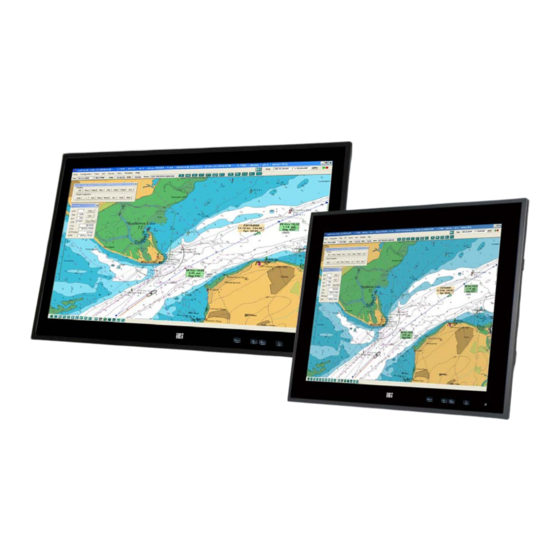
1.1 Overview Figure 1-1: S19A-QM87i Marine Panel PC The S19A/S24A-QM87i series is a 19”/24” marine panel PC with Intel® Core™ i5-4400E processor and Intel® QM87 Express Chipset. The S19A/S24A-QM87i is preinstalled with 4 GB of DDR3 SO-DIMM and can accommodate up to 16 GB of DDR3 memory. Storage in the system is handled by two 2.5”... -
Page 15: Front Panel
RoHS compliant design 1.3 Front Panel The front side of the S19A/S24A-QM87i (Figure 1-2) is a flat panel LCD screen surrounded by an aluminum frame. The bottom frame includes four OSD buttons and an ambient light sensor. Figure 1-2: S24A-QM87i Front Panel... -
Page 16: Display Control Buttons
OSD (on-screen display). Please refer to Chapter 4 for more detail. Figure 1-3: Display Control Buttons 1.4 Top Panel The top panel of the S19A/S24A-QM87i provides access to the following external I/O connectors and LED indicators: ... -
Page 17: Bottom Panel
COM port mode, please change the BIOS options in Advanced F81866 Super IO Configuration Serial Port Configuration (refer to Section 5.3.10.1). 1.5 Bottom Panel The S19A/S24A-QM87i bottom panel provides access to the following external I/O connectors: 1 x 18 V–36 V DC input terminal block ... -
Page 18: Rear Panel
S19A/S24A-QM87i Marine Panel PC Figure 1-5: Bottom Panel 1.6 Rear Panel The rear panel is installed with a SBOX marine computer which can be easily uninstalled from the display panel. In addition, there are some ventilation vents, cable tie holders and several mounting holes for panel mount and stand mount. -
Page 19: Technical Specifications
S19A/S24A-QM87i Marine Panel PC 1.7 Technical Specifications The specifications for the S19A/S24A-QM87i are listed below. S19A-QM87i S24A-QM87i LCD Size 19” 24” Panel Type PMVA AMVA Max. Resolution 1280 x 1024 (5:4) 1920 x 1080 (16:9) Contrast Ratio 2000:1 5000:1 Brightness (cd/m2) LCD Color 16.7M... - Page 20 S19A/S24A-QM87i Marine Panel PC Display 1 x DVI-D connector 1 x HDMI connector 1 x VGA connector Serial Port 1 x RS-232 DB-9 serial port (non-isolated) 4 x RS-232/422/485 DB-9 serial port (2.5 kV isolation protection) 2 x USB 2.0 port 2 x USB 3.0 port...
-
Page 21: Table 1-1: Technical Specifications
Auto-diming function is not covered by DNV-GL certification (the function is disabled by default). Touch-screen function is not covered by DNV-GL certification. Not connected I/O ports need to be protected by protection caps (the S19A/S24A-QM87i is shipped with all I/O ports protected by caps). Page 9... -
Page 22: Dimensions
S19A/S24A-QM87i Marine Panel PC 1.8 Dimensions The physical dimensions of the S19A-QM87i are shown in Figure 1-7. Figure 1-7: S19A-QM87i Dimensions (mm) Page 10... -
Page 23: Figure 1-8: S24A-Qm87I Dimensions (Mm)
S19A/S24A-QM87i Marine Panel PC The physical dimensions of the S24A-QM87i are shown in Figure 1-8. Figure 1-8: S24A-QM87i Dimensions (mm) Page 11... -
Page 24: Unpacking
S19A/S24A-QM87i Marine Panel PC Chapter Unpacking Page 12... -
Page 25: Anti-Static Precautions
Electrostatic discharge (ESD) can cause serious damage to electronic components, including the S19A/S24A-QM87i. Dry climates are especially susceptible to ESD. It is therefore critical that whenever the S19A/S24A-QM87i or any other electrical component is handled, the following anti-static precautions are strictly adhered to. -
Page 26: Unpacking Checklist
If some of the components listed in the checklist below are missing, please do not proceed with the installation. Contact the IEI reseller or vendor you purchased the S19A/S24A-QM87i from or contact an IEI sales representative directly. To contact an IEI sales representative, please send an email to sales@ieiworld.com. -
Page 27: Optional Items
S19A/S24A-QM87i Marine Panel PC 2.4 Optional Items The following are optional components which may be separately purchased: Item and Part Number Image IPMI 2.0 adapter card with AST2400 BMC chip (P/N: iRIS-2400-R10) Panel mounting kit (P/N: PK-S19A-R10) (P/N: PK-S24A-R10) Desktop stand kit... -
Page 28: Installation
S19A/S24A-QM87i Marine Panel PC Chapter Installation Page 16... -
Page 29: Installation Precautions
Electric shock and personal injury might occur if the rear panel of the S19A/S24A-QM87i is opened while the power cord is still connected to an electrical outlet. -
Page 30: Cfast Card Installation
3.2 CFast Card Installation The S19A/S24A-QM87i series has a CFast card slot on the rear panel. To install the CFast card into the system, please follow the steps below. -
Page 31: Hdd Installation
Secure the CFast card with the slot cover by fastening the previously removed retention screw. 3.3 HDD Installation The S19A/S24A-QM87i has two 2.5” HDD bays inside the SBOX computer, which is attached to the rear panel of the system. To install HDDs, follow the steps below. Step 1: Remove the SBOX computer from the S19A/S24A-QM87i rear panel by removing/loosing the six retention screws indicated in Figure 3-3. -
Page 32: Figure 3-4: Bottom Cover Retention Screws
S19A/S24A-QM87i Marine Panel PC Step 2: Remove the bottom cover of the SBOX by removing the 11 retention screws on the bottom panel. See Figure 3-4. Figure 3-4: Bottom Cover Retention Screws Step 3: Locate the HDD brackets inside the bottom cover. Remove the four HDD bracket retention screws of one of the HDD brackets and lift the HDD bracket. -
Page 33: Figure 3-6: Inserting The Hdd
Step 7: Connect the SATA cables and the SATA power cables to the motherboard. Step 8: Reinstall the bottom cover with the previously removed retention screws. Step 9: Reinstall the SBOX computer onto the rear panel of the S19A/S24A-QM87i. Page 21... -
Page 34: At/Atx Mode Selection
S19A/S24A-QM87i Marine Panel PC 3.4 AT/ATX Mode Selection AT and ATX power modes can both be used on the S19A/S24A-QM87i panel PC. The selection is made through an AT/ATX switch on the I/O interface panel. The switch is shown below. -
Page 35: Panel Mounting
S19A/S24A-QM87i Marine Panel PC 3.5.1 Panel Mounting To mount the S19A/S24A-QM87i flat panel PC into a panel, please follow the steps below. Step 1: Select the position on the panel to mount the flat panel PC. Step 2: Cut out a section from the panel that corresponds to the rear panel dimensions of the flat panel PC. -
Page 36: Figure 3-11: S19A-Qm87I Panel Mounting Hole Covers
S19A/S24A-QM87i Marine Panel PC Step 4: Remove the panel mounting hole covers from the rear panel. Each cover is secured to the rear panel with a retention screw. Remove the retention screw to remove the cover. Figure 3-11: S19A-QM87i Panel Mounting Hole Covers... -
Page 37: Stand Mounting
3.5.2 Stand Mounting To mount the S19A/S24A-QM87i using the optional stand mounting kit, please follow the steps below. Step 1: Locate the screw holes on the rear of the S19A/S24A-QM87i. This is where the brackets will be attached. Page 25... -
Page 38: Figure 3-14: S19A-Qm87I Stand Mounting Screw Holes
Figure 3-14: S19A-QM87i Stand Mounting Screw Holes Figure 3-15: S24A-QM87i Stand Mounting Screw Holes Step 2: Align the brackets with the screw holes. Step 3: To secure the brackets to the S19A/S24A-QM87i insert the retention screws into the screw holes and tighten them. Page 26... -
Page 39: Ceiling Mounting
0 : Figure 3-17: Stand Mounting Method 2 3.5.3 Ceiling Mounting To mount the S19A/S24A-QM87i using the optional ceiling mounting kit, please follow the steps below. Step 1: Select a location on the ceiling for the ceiling mounting brackets. -
Page 40: Figure 3-18: Locations Of Bracket Screw Holes For S19A-Qm87I
S19A/S24A-QM87i Marine Panel PC Figure 3-18: Locations of Bracket Screw Holes for S19A-QM87i Figure 3-19: Locations of Bracket Screw Holes for S24A-QM87i Step 3: Drill six pilot holes at the marked locations on the ceiling for the bracket retention screws. -
Page 41: Figure 3-20: Ceiling Mounting Bracket Adjustment
S19A/S24A-QM87i Marine Panel PC Figure 3-20: Ceiling Mounting Bracket Adjustment Step 5: Remove the four knockout holes on the side panels (two on each side). See Figure 3-21. Figure 3-21: Knockout Holes for Ceiling Mounting Brackets Step 6: Align the rivets on the mounting brackets with the mounting holes on the side panels. -
Page 42: Figure 3-22: Installing Ceiling Mounting Bracket (One Side)
S19A/S24A-QM87i Marine Panel PC Step 7: Carefully insert the rivets through the holes and pull the bracket downwards until the bracket rest securely in the slotted holes. Then, insert a captive screw and tighten it firmly to secure the bracket. See Figure 3-22. -
Page 43: Figure 3-23: Ceiling Mounting
S19A/S24A-QM87i Marine Panel PC Figure 3-23: Ceiling Mounting Step 11: The ceiling mounting brackets can also be used to mount on other surfaces. To do so, simply install the brackets the other way around as shown in Figure 3-24. Figure 3-24: Alternative of Ceiling Mounting Brackets... -
Page 44: Serial Device Connection
S19A/S24A-QM87i Marine Panel PC 3.6 Serial Device Connection The S19A/S24A-QM87i series has five serial ports, including four RS-232/422/484 ports on the front panel and one RS-232 port on the rear panel. The port locations are shown in Figure 3-25. The pinouts of the serial ports are listed in the following sections. -
Page 45: Serial Port (Com1)
S19A/S24A-QM87i Marine Panel PC 3.6.1 RS-232 Serial Port (COM1) The pinouts of the RS-232 serial port are listed in the following table. PIN NO. DESCRIPTION PIN NO. DESCRIPTION Table 3-1: RS-232 Serial Port (COM1) Pinouts 3.6.2 RS-232/422/485 Serial Port (COM2–COM5) The RS-232/422/485 mode selection of COM2–COM5 is made through the system BIOS. -
Page 46: Can Bus Connection And Configuration
S19A/S24A-QM87i Marine Panel PC 3.7 CAN Bus Connection and Configuration The S19A/S24A-QM87i has a CAN bus connector for CAN-bus connection. The pinouts for the CAN bus connector are listed in the figure and table below. Figure 3-26: CAN Bus Connector PIN NO. -
Page 47: Powering On The System
S19A/S24A-QM87i Marine Panel PC Figure 3-27: CAN Bus Jumper Locations JP1 & JP2 DESCRIPTION Short Long wire transmitting Open Normal Table 3-4: CAN Bus Jumper Settings 3.8 Powering On the System To power on the system, follow the steps below: Step 1: Connect the power cable to the 3-pin power input terminal block. -
Page 48: Clear Cmos
Figure 3-29: Power Connector and Power Button 3.9 Clear CMOS If the S19A/S24A-QM87i fails to boot due to improper BIOS settings, the clear CMOS button clears the CMOS data and resets the system BIOS information. To do this, push the clear CMOS button for three seconds, and then restart the system. The clear CMOS button location is shown in Figure 3-30. -
Page 49: Driver Installation
Visit the IEI website or contact technical support for the latest updates. All the drivers for the S19A/S24A-QM87i are on the utility CD that came with the system. The utility CD contains drivers for Windows 7 and Windows 8 operating systems. Please select the corresponding drivers for the system and follow the step-by-step procedure to install each driver. -
Page 50: Ipmi Setup Procedure
Management Interface (IPMI) that helps lower the overall costs of server management by enabling users to maximize IT resources, save time and manage multiple systems. The S19A/S24A-QM87i supports IPMI 2.0 through the optional iRIS-2400 module. Follow the steps below to setup IPMI. -
Page 51: Figure 3-31: Iei Iman Web Address
S19A/S24A-QM87i Marine Panel PC e. A serial of number shows. The last four two-digit hexadecimal numbers are the IP address. Convert the hexadecimal numbers to decimal numbers. Step 2: On the remote management console, open a web browser. Enter the managed system IP address in the web browser (Figure 3-31). - Page 52 S19A/S24A-QM87i Marine Panel PC NOTE: To understand how to use the IEI iMAN Web GUI, please refer to the iRIS-2400 Web GUI user manual in the utility CD came with the S19A/S24A-QM87i. The user manual describes each function in detail. Page 40...
-
Page 53: On-Screen-Display (Osd) Controls
S19A/S24A-QM87i Marine Panel PC Chapter On-Screen-Display (OSD) Controls Page 41... -
Page 54: User Mode Osd Structure
S19A/S24A-QM87i Marine Panel PC 4.1 User Mode OSD Structure 4.1.1 OSD Buttons The OSD control buttons are located on the bottom right corner of the front panel. Figure 4-1: OSD Button Locations The function of each button is described in the following table. -
Page 55: Osd Menu Structure
S19A/S24A-QM87i Marine Panel PC 4.1.2 OSD Menu Structure Table 4-2 shows the OSD menu structure for all models of theS19A/S24A-QM87i series panel PC. Level 0 Level 1 Value Image Menu Backlight 0 to 100 Brightness 0 to 100 Contrast 0 to 100... -
Page 56: Using The Osd
S19A/S24A-QM87i Marine Panel PC 4.2 Using the OSD OSD menu options are described below. 4.2.1 Image Menu Image menu options are shown in Figure 4-2. Figure 4-2: Image Menu Backlight Adjusts the backlight brightness of screen. Brightness Adjusts the brightness of screen. Setting this value too high or too low will affect the quality of image. -
Page 57: System Menu
S19A/S24A-QM87i Marine Panel PC Color Fine-tunes the palette of color hues 4.2.2 System Menu System options are shown in Figure 4-3. Figure 4-3: System Menu OSD Settings This item allows adjustment of the following items: Timer–Determines how many seconds the OSD menu stays on screen before it disappears when OSD is left unattended. - Page 58 S19A/S24A-QM87i Marine Panel PC OSD buttons when OSD menu is off Keypad LED 2–Control the brightness of the physical OSD buttons when OSD menu is on Reset Restores the default OSD settings. Note that this will restore all default display settings.
-
Page 59: Bios Setup
S19A/S24A-QM87i Marine Panel PC Chapter BIOS Setup Page 47... -
Page 60: Introduction
S19A/S24A-QM87i Marine Panel PC 5.1 Introduction The BIOS is programmed onto the BIOS chip. The BIOS setup program allows changes to certain system settings. This chapter outlines the options that can be changed. NOTE: Some of the BIOS options may vary throughout the life cycle of the product and are subject to change without prior notice. -
Page 61: Getting Help
S19A/S24A-QM87i Marine Panel PC Function Decrease the numeric value or make changes Page Up key Increase the numeric value or make changes Page Dn key Decrease the numeric value or make changes Esc key Main Menu – Quit and not save changes into CMOS... -
Page 62: Main
S19A/S24A-QM87i Marine Panel PC 5.2 Main The Main BIOS menu (BIOS Menu 1) appears when the BIOS Setup program is entered. The Main menu gives an overview of the basic system information. Aptio Setup Utility – Copyright (C) 2012 American Megatrends, Inc. -
Page 63: Advanced
S19A/S24A-QM87i Marine Panel PC The System Overview field has two user configurable fields: System Date [xx/xx/xx] Use the System Date option to set the system date. Manually enter the day, month and year. System Time [xx:xx:xx] Use the System Time option to set the system time. Manually enter the hours, minutes and seconds. -
Page 64: Acpi Settings
S19A/S24A-QM87i Marine Panel PC 5.3.1 ACPI Settings The ACPI Settings menu (BIOS Menu 3) configures the Advanced Configuration and Power Interface (ACPI) options. Aptio Setup Utility – Copyright (C) 2012 American Megatrends, Inc. Advanced ACPI Settings Select ACPI sleep state... -
Page 65: Rtc Wake Settings
S19A/S24A-QM87i Marine Panel PC 5.3.2 RTC Wake Settings The RTC Wake Settings menu (BIOS Menu 4) configures RTC wake event. Aptio Setup Utility – Copyright (C) 2012 American Megatrends, Inc. Advanced Wake system with Fixed Time [Disabled] Enable or disable System wake on alarm event. -
Page 66: Trusted Computing
S19A/S24A-QM87i Marine Panel PC Enabled If selected, the following appears with values that can be selected: *Wake up every day *Wake up date *Wake up hour *Wake up minute *Wake up second After setting the alarm, the computer turns itself on from a suspend state when the alarm goes off. -
Page 67: Cpu Configuration
S19A/S24A-QM87i Marine Panel PC Security Device Support [Disable] Use the Security Device Support option to configure support for the security devices. Security device support is disabled. Disable EFAULT Security device support is enabled. Enable 5.3.4 CPU Configuration Use the CPU Configuration menu (BIOS Menu 6) to view detailed CPU specifications and configure the CPU. - Page 68 S19A/S24A-QM87i Marine Panel PC CPU Signature: Lists the CPU signature value. Microcode Patch: Lists the microcode patch being used. Max CPU Speed: Lists the maximum CPU processing speed. Min CPU Speed: Lists the minimum CPU processing speed.
-
Page 69: Intel Virtualization Technology [Disabled]
S19A/S24A-QM87i Marine Panel PC Intel Virtualization Technology [Disabled] Use the Intel Virtualization Technology option to enable or disable virtualization on the system. When combined with third party software, Intel® Virtualization technology allows several OSs to run on the same system at the same time. -
Page 70: Sata Configuration
S19A/S24A-QM87i Marine Panel PC 5.3.5 SATA Configuration Use the SATA Configuration menu (BIOS Menu 7) to change and/or set the configuration of the SATA devices installed in the system. Aptio Setup Utility – Copyright (C) 2012 American Megatrends, Inc. Advanced... -
Page 71: Intel Rapid Start Technology
S19A/S24A-QM87i Marine Panel PC 5.3.6 Intel Rapid Start Technology The Intel Rapid Start Technology menu (BIOS Menu 8) configures Intel® Rapid Start Technology. Aptio Setup Utility – Copyright (C) 2012 American Megatrends, Inc. Advanced Intel(R) Rapid Start Technology [Disabled] Enable or disable... -
Page 72: Amt Configuration
S19A/S24A-QM87i Marine Panel PC 5.3.7 AMT Configuration The AMT Configuration menu (BIOS Menu 9) allows advanced power management options to be configured. Aptio Setup Utility – Copyright (C) 2012 American Megatrends, Inc. Advanced Intel AMT [Enabled] Enable/Disable Intel(R) Un-Configure ME... -
Page 73: Usb Configuration
S19A/S24A-QM87i Marine Panel PC Enabled Enable ME unconfigure 5.3.8 USB Configuration Use the USB Configuration menu (BIOS Menu 10) to read USB configuration information and configure the USB settings. Aptio Setup Utility – Copyright (C) 2012 American Megatrends, Inc. -
Page 74: Iwdd H/W Monitor
S19A/S24A-QM87i Marine Panel PC Enabled Legacy USB support enabled EFAULT Legacy USB support disabled Disabled Auto Legacy USB support disabled if no USB devices are connected 5.3.9 iWDD H/W Monitor The iWDD H/W Monitor menu (BIOS Menu 11) displays operating temperature and system voltages. -
Page 75: F81866 Super Io Configuration
S19A/S24A-QM87i Marine Panel PC +5VSB +3.3V +3.3VSB 5.3.10 F81866 Super IO Configuration Use the F81866 Super IO Configuration menu (BIOS Menu 12) to set or change the configurations for the serial ports. Aptio Setup Utility – Copyright (C) 2012 American Megatrends, Inc. -
Page 76: Serial Port N Configuration
S19A/S24A-QM87i Marine Panel PC 5.3.10.1 Serial Port n Configuration Use the Serial Port n Configuration menu (BIOS Menu 13) to configure the serial port n. Aptio Setup Utility – Copyright (C) 2012 American Megatrends, Inc. Advanced Serial Port 1 Configuration... -
Page 77: Change Settings [Auto]
S19A/S24A-QM87i Marine Panel PC IO=3E8h; Serial Port I/O port address is 3E8h and the interrupt IRQ=3, 4 address is IRQ3, 4 Serial Port I/O port address is 2F8h and the interrupt IO=2F8h; address is IRQ3, 4 IRQ=3, 4 ... - Page 78 S19A/S24A-QM87i Marine Panel PC IO=2C8h; Serial Port I/O port address is 2C8h and the interrupt IRQ=3, 4 address is IRQ3, 4 Serial Port Mode [RS485] Use the Serial Port Mode option to set the Serial Port 2 signaling mode.
- Page 79 S19A/S24A-QM87i Marine Panel PC IO=2D0h; Serial Port I/O port address is 2D0h and the interrupt IRQ=10, 11 address is IRQ10, 11 Serial Port I/O port address is 2D8h and the interrupt IO=2D8h; address is IRQ10, 11 IRQ=10, 11 ...
- Page 80 S19A/S24A-QM87i Marine Panel PC IO=2E8h; Serial Port I/O port address is 2E8h and the interrupt IRQ=10, 11 address is IRQ10, 11 Serial Port I/O port address is 2D0h and the interrupt IO=2D0h; address is IRQ10, 11 IRQ=10, 11 ...
-
Page 81: Serial Port Console Redirection
S19A/S24A-QM87i Marine Panel PC IO=2C0h; Serial Port I/O port address is 2C0h and the interrupt IRQ=10, 11 address is IRQ10, 11 Serial Port I/O port address is 2C8h and the interrupt IO=2C8h; address is IRQ10, 11 IRQ=10, 11 ... -
Page 82: Console Redirection [Enabled]
S19A/S24A-QM87i Marine Panel PC Aptio Setup Utility – Copyright (C) 2012 American Megatrends, Inc. Advanced COM1 Console Redirection Console Redirection [Disabled] Enable/Disable > Console Redirection Settings COM2 Console Redirection [Disabled] > Console Redirection Settings COM3 Console Redirection [Disabled] > Console Redirection Settings... -
Page 83: Iei Feature
S19A/S24A-QM87i Marine Panel PC 5.3.12 IEI Feature Use the IEI Feature menu (BIOS Menu 15) to configure One Key Recovery function. Aptio Setup Utility – Copyright (C) 2012 American Megatrends, Inc. Advanced iEi Feature Auto Recovery Function Reboot and recover... -
Page 84: Chipset
S19A/S24A-QM87i Marine Panel PC 5.4 Chipset Use the Chipset menu (BIOS Menu 16) to configure the system chipset. Aptio Setup Utility – Copyright (C) 2012 American Megatrends, Inc. Main Advanced Chipset Boot Security Save & Exit Server Mgmt > PCH-IO Configuration PCH Parameters >... -
Page 85: Restore On Ac Power Loss [Last State]
S19A/S24A-QM87i Marine Panel PC Restore on AC Power Loss [Last State] Use the Restore on AC Power Loss BIOS option to specify what state the system returns to if there is a sudden loss of power to the system. -
Page 86: System Agent (Sa) Configuration
S19A/S24A-QM87i Marine Panel PC 5.4.2 System Agent (SA) Configuration Use the System Agent (SA) Configuration menu (BIOS Menu 18) to configure the System Agent (SA) parameters. Aptio Setup Utility – Copyright (C) 2012 American Megatrends, Inc. Chipset VT-d Capability Supported... -
Page 87: Graphics Configuration
S19A/S24A-QM87i Marine Panel PC 5.4.2.1 Graphics Configuration Use the Graphics Configuration submenu (BIOS Menu 19) to configure the graphics settings. Aptio Setup Utility – Copyright (C) 2012 American Megatrends, Inc. Chipset Graphics Configuration Select which of Primary Display [Auto] IGFX/PEG/PCI Graphics... -
Page 88: Dvmt Total Gfx Mem [256M]
S19A/S24A-QM87i Marine Panel PC 128M 256M Default 512M DVMT Total Gfx Mem [256M] Use the DVMT Total Gfx Mem option to select DVMT5.0 total graphic memory size used by the internal graphic device. The following options are available: ... -
Page 89: Memory Configuration
S19A/S24A-QM87i Marine Panel PC 5.4.3 Memory Configuration Use the Memory Configuration submenu (BIOS Menu 20) to display the memory information. Aptio Setup Utility – Copyright (C) 2012 American Megatrends, Inc. Chipset Memory Information Memory Frequency 1600 Mhz Total Memory 4096 MB (DDR3) --------------------- : Select Screen... -
Page 90: Bootup Numlock State [On]
S19A/S24A-QM87i Marine Panel PC Bootup NumLock State [On] Use the Bootup NumLock State BIOS option to specify if the number lock setting must be modified during boot up. Allows the Number Lock on the keyboard to be EFAULT enabled automatically when the computer system boots up. -
Page 91: Security
S19A/S24A-QM87i Marine Panel PC Launch PXE OpROM [Disabled] Use the Launch PXE OpROM option to enable or disable boot option for legacy network devices. Disabled Ignore all PXE Option ROMs EFAULT Load PXE Option ROMs Enabled ... -
Page 92: Save & Exit
S19A/S24A-QM87i Marine Panel PC User Password Use the User Password to set or change a user password. 5.7 Save & Exit Use the Save & Exit menu (BIOS Menu 23) to load default BIOS values, optimal failsafe values and to save configuration changes. -
Page 93: Server Management
S19A/S24A-QM87i Marine Panel PC Save as User Defaults Use the Save as User Defaults option to save the changes done so far as user defaults. Restore User Defaults Use the Restore User Defaults option to restore the user defaults to all the setup options. -
Page 94: System Event Log
S19A/S24A-QM87i Marine Panel PC 5.8.1 System Event Log Use the System Event Log menu (BIOS Menu 25) to configure the system event log of the BMC. Aptio Setup Utility – Copyright (C) 2012 American Megatrends, Inc. Server Mgmt Enabling/Disabling Options... - Page 95 S19A/S24A-QM87i Marine Panel PC Yes, On Erase system event log on every reset. every reset When SEL is Full [Do Nothing] Use the When SEL is Full option to select an reaction to a full SEL. Do not do anything when SEL is full.
-
Page 96: Bmc Network Configuration
S19A/S24A-QM87i Marine Panel PC 5.8.2 BMC Network Configuration Use the BMC Network Configuration menu (BIOS Menu 26) to configure the BMC network parameters. Aptio Setup Utility – Copyright (C) 2012 American Megatrends, Inc. Server Mgmt BMC network configuration Select to configure LAN... -
Page 97: Maintenance
S19A/S24A-QM87i Marine Panel PC Chapter Maintenance Page 85... -
Page 98: System Maintenance Overview
Failure to follow these instructions may lead to personal injury and system damage. To preserve the working integrity of the S19A/S24A-QM87i, the system must be properly maintained. If internal components need replacement, the proper maintenance procedures must be followed to ensure the system can continue to operate normally. -
Page 99: Figure 6-1: Sbox Computer Retention Screws
To replace a SO-DIMM into a SO-DIMM socket, please follow the steps below. Step 1: Remove the SBOX computer from the S19A/S24A-QM87i rear panel by removing/loosing the six retention screws indicated in Figure 6-1. Slide the SBOX computer downward and lift the SBOX. -
Page 100: Figure 6-2: Bottom Cover Retention Screws
S19A/S24A-QM87i Marine Panel PC Step 2: Remove the bottom cover by removing the 11 retention screws. Figure 6-2: Bottom Cover Retention Screws Step 3: Locate the SO-DIMM. (Figure 6-3). Figure 6-3: SO-DIMM Locations Step 4: Remove the cable tie that secures the heatsink with the SO-DIMM. Then, remove the heatsink. -
Page 101: Figure 6-4: So-Dimm Installation
Step 8: Place the heatsink and use a cable tie to secure the heatsink with the SO-DIMM. Step 9: Reinstall the bottom cover. Step 10: Reinstall the SBOX computer onto the rear panel of the S19A/S24A-QM87i. Step 0: Page 89... -
Page 102: Interface Connectors
S19A/S24A-QM87i Marine Panel PC Chapter Interface Connectors Page 90... -
Page 103: Peripheral Interface Connectors
S19A/S24A-QM87i Marine Panel PC 7.1 Peripheral Interface Connectors The S19A/S24A-QM87i motherboard comes with a number of peripheral interface connectors and configuration jumpers. The connector locations are shown in Figure 7-1 and Figure 7-2. The Pin 1 locations of the on-board connectors are also indicated in the diagrams below. -
Page 104: Figure 7-2: Main Board Layout Diagram (Solder Side)
S19A/S24A-QM87i Marine Panel PC Figure 7-2: Main Board Layout Diagram (Solder Side) Page 92... -
Page 105: Internal Peripheral Connectors
Internal peripheral connectors are found on the motherboard and are only accessible when the motherboard is outside of the chassis. The table below shows a list of the peripheral interface connectors on the S19A/S24A-QM87i motherboard. Pinouts of these connectors can be found in the following sections. -
Page 106: Audio Connector (Audio1)
S19A/S24A-QM87i Marine Panel PC Connector Type Label SMBus connector 4-pin wafer SMB1 SO-DIMM connectors SO-DIMM connector DIMM1, DIMM2 SPI Flash connector 6-pin wafer SPI1 SPI Flash connector (EC) 2-pin header TPM connector 20-pin header TPM1 Table 7-1: Peripheral Interface Connectors 7.2.1 Audio Connector (AUDIO1) -
Page 107: Digital I/O Connector (Dio1)
S19A/S24A-QM87i Marine Panel PC 7.2.4 Digital I/O Connector (DIO1) PIN NO. DESCRIPTION PIN NO. DESCRIPTION DOUT3 DOUT2 DOUT1 DOUT0 DIN3 DIN2 DIN1 DIN0 Table 7-5: Digital I/O Connector (DIO1) Pinouts 7.2.5 EC Debug Connector (LPT_DB1) PIN NO. DESCRIPTION PIN NO. -
Page 108: Front Panel Connector (F_Panel1)
S19A/S24A-QM87i Marine Panel PC 7.2.7 Front Panel Connector (F_PANEL1) DESCRIPTION DESCRIPTION Power LED PWR_LED+ Speaker SPKR+ PWR_LED+ IPMI LED IPMI ID_LED+ PWR_LED- IPMI ID_LED- Power PWR_BTN+ Speaker SPKR- Button PWR_BTN- HDD LED HDD_LED+ RESET+ HDD_LED- RESET- Table 7-8: Front Panel Connector (F_PANEL1) Pinouts 7.2.8 IPMI LED Connector (IPMI_LED1) -
Page 109: Power Connector (Pwr1)
S19A/S24A-QM87i Marine Panel PC PIN NO. DESCRIPTION PIN NO. DESCRIPTION CLK- CLK+ PCIRST# VCC3 PCIRST# PERN2 3VDual PERP2 1.5V SMBCLK PETN2 SMBDATA PETP2 USBD- USBD+ 1.5V VCC3 Table 7-11: PCIe Mini Slots (MINI-PCIE1, MINI-PCIE2) Pinouts 7.2.11 Power Connector (PWR1) PIN NO. -
Page 110: Power Button Connector (Pwr_Btn1)
S19A/S24A-QM87i Marine Panel PC 7.2.12 Power Button Connector (PWR_BTN1) PIN NO. DESCRIPTION PWRBTN_SW# Table 7-13: Power Button Connector (PWR_BTN1) Pinouts 7.2.13 PS_ON Connector (PS_ON1) PIN NO. DESCRIPTION 5VSB EC_PSON# Table 7-14: PS_ON Connector (PS_ON1) Pinouts 7.2.14 RS-232/422/485 Connector (COM2, COM3, COM4, COM5) PIN NO. -
Page 111: Sata Connector (S_Ata2)
S19A/S24A-QM87i Marine Panel PC Table 7-16: SATA Connector (S_ATA1) Pinouts 7.2.16 SATA Connector (S_ATA2) PIN NO. DESCRIPTION Table 7-17: SATA Connector (S_ATA2) Pinouts 7.2.17 SATA Power Connector (SATA_PWR1) Total +5V SATA power is 3A (SATA_PWR1plus SATA_PWR2) Total +12V SATA power is 3A (SATA_PWR1plus SATA_PWR2) PIN NO. -
Page 112: Sata Power Connector (Sata_Pwr2)
S19A/S24A-QM87i Marine Panel PC 7.2.18 SATA Power Connector (SATA_PWR2) PIN NO. DESCRIPTION +12V Table 7-19: SATA Power Connector (SATA_PWR2) Pinouts 7.2.19 SMBus Connector, EC (SMB1) PIN NO. DESCRIPTION SMB_DATA SMB_CLK +V5S Table 7-20: SMBus Connector, EC (SMB1) 7.2.20 SPI Flash Connector (SPI1) PIN NO. -
Page 113: Spi Flash Connector, Ec (Cn2)
GLKRUN# LPCPD# LDRQ# Table 7-23: TPM Connector (TPM1) Pinouts 7.3 External Interface Panel Connectors The table below lists the rear panel connectors on the S19A/S24A-QM87i motherboard. Pinouts of these connectors can be found in the following sections. Connector Type Label... -
Page 114: Can Bus Connector (Can1)
S19A/S24A-QM87i Marine Panel PC Connector Type Label HDMI connector HDMI HDMI1 Keyboard/mouse and USB 2.0 combo connector PS/2 K/B_USB1 USB 2.0 port GbE connectors RJ-45 LAN1/2-CN1 RS-232 serial port DB-9 COM1 USB 3.0 connectors USB 3.0 port USB3_CN1 Table 7-24: Rear Panel Connectors 7.3.1 CAN Bus Connector (CAN1) -
Page 115: Vga Connector (Vga1)
S19A/S24A-QM87i Marine Panel PC 7.3.3 VGA Connector (VGA1) PIN NO. DESCRIPTION PIN NO. DESCRIPTION GREEN GROUND BLUE DDCDA GROUND HSYNC GROUND VSYNC GROUND DDCCLK GROUND Table 7-27: VGA Connector (VGA1) Pinouts 7.3.4 HDMI Connector (HDMI1) PIN NO. DESCRIPTION PIN NO. -
Page 116: Gbe Connectors (Lan1/2-Cn1)
S19A/S24A-QM87i Marine Panel PC 7.3.5 GbE Connectors (LAN1/2-CN1) PIN NO. DESCRIPTION PIN NO. DESCRIPTION MDIA3- MDIA2+ MDIA3+ MDIA1+ MDIA1- MDIA0- MDIA2- MDIA0+ Table 7-29: RJ-45 GbE Connector (LAN1/2-CN1) Pinouts 7.3.6 RS-232 Serial Port (COM1) PIN NO. DESCRIPTION PIN NO. DESCRIPTION Table 7-30: RS-232 Serial Port (COM1) Pinouts 7.3.7 USB 2.0 Connectors (USB1) -
Page 117: Usb 3.0 Connectors (Usb3_Cn1)
S19A/S24A-QM87i Marine Panel PC 7.3.8 USB 3.0 Connectors (USB3_CN1) PIN NO. DESCRIPTION PIN NO. DESCRIPTION USB_DATA- USB_DATA- USB_DATA+ USB_DATA+ USB3_RX- USB3_RX- USB3_RX+ USB3_RX+ USB3_TX- USB3_TX- USB3_TX+ USB3_TX+ Table 7-32: USB 3.0 Connector (USB3_CN1) Pinouts Page 105... -
Page 118: A Regulatory Compliance
S19A/S24A-QM87i Marine Panel PC Appendix Regulatory Compliance Page 106... - Page 119 S19A/S24A-QM87i Marine Panel PC DECLARATION OF CONFORMITY This equipment is in conformity with the following EU directives: EMC Directive 2004/108/EC Low-Voltage Directive 2006/95/EC RoHS II Directive 2011/65/EU If the user modifies and/or install other devices in the equipment, the CE conformity declaration may no longer apply.
- Page 120 S19A/S24A-QM87i Marine Panel PC Español [Spanish] IEI Integration Corp declara que el equipo cumple con los requisitos esenciales y cualesquiera otras disposiciones aplicables o exigibles de la Directiva 1999/5/CE. Ελληνική [Greek] IEI Integration Corp ΔΗΛΩΝΕΙ ΟΤΙ ΕΞΟΠΛΙΣΜΟΣ ΣΥΜΜΟΡΦΩΝΕΤΑΙ ΠΡΟΣ ΤΙΣ...
- Page 121 S19A/S24A-QM87i Marine Panel PC Româna [Romanian] IEI Integration Corp declară că acest echipament este in conformitate cu cerinţele esenţiale şi cu celelalte prevederi relevante ale Directivei 1999/5/CE. Slovensko [Slovenian] IEI Integration Corp izjavlja, da je ta opreme v skladu z bistvenimi zahtevami in ostalimi relevantnimi določili direktive 1999/5/ES.
- Page 122 S19A/S24A-QM87i Marine Panel PC FCC WARNING This equipment complies with Part 15 of the FCC Rules. Operation is subject to the following two conditions: This device may not cause harmful interference, and This device must accept any interference received, including interference that may cause undesired operation.
-
Page 123: B Safety Precautions
S19A/S24A-QM87i Marine Panel PC Appendix Safety Precautions Page 111... -
Page 124: Safety Precautions
Do not apply voltage levels that exceed the specified voltage range. Doing so may cause fire and/or an electrical shock. Electric shocks can occur if the S19A/S24A-QM87i chassis is opened when the S19A/S24A-QM87i is running. Do not drop or insert any objects into the ventilation openings of the S19A/S24A-QM87i. -
Page 125: Anti-Static Precautions
Electrostatic discharge (ESD) can cause serious damage to electronic components, including the S19A/S24A-QM87i. Dry climates are especially susceptible to ESD. It is therefore critical that whenever the S19A/S24A-QM87i is opened and any of the electrical components are handled, the following anti-static precautions are strictly adhered to. -
Page 126: Product Disposal
Please follow the national guidelines for electrical and electronic product disposal. B.2 Maintenance and Cleaning Precautions When maintaining or cleaning the S19A/S24A-QM87i, please follow the guidelines below. B.2.1 Maintenance and Cleaning Prior to cleaning any part or component of the S19A/S24A-QM87i, please read the details below. Page 114... -
Page 127: Cleaning Tools
Some components in the S19A/S24A-QM87i may only be cleaned using a product specifically designed for the purpose. In such case, the product will be explicitly mentioned in the cleaning tips. Below is a list of items to use when cleaning the S19A/S24A-QM87i. ... -
Page 128: Cbios Menu Options
S19A/S24A-QM87i Marine Panel PC Appendix BIOS Menu Options Page 116... -
Page 129: Bios Configuration Options
S19A/S24A-QM87i Marine Panel PC C.1 BIOS Configuration Options Below is a list of BIOS configuration options described in Chapter 4. System Date [xx/xx/xx] ......................51 System Time [xx:xx:xx] ....................... 51 ACPI Sleep State [S1 only (CPU Stop Clock)] ..............52 Wake System with Fixed Time [Disabled] ................. - Page 130 S19A/S24A-QM87i Marine Panel PC Serial Port Mode [RS485] ....................69 Console Redirection [Enabled]................... 70 Auto Recovery Function [Disabled] ................... 71 Restore on AC Power Loss [Last State] ................73 Azalia (HD Audio) [Enabled] ....................73 Serial IRQ Mode [Continuous] .................... 73 Power Saving Function (ERP) [Disabled] ................
-
Page 131: D Watchdog Timer
S19A/S24A-QM87i Marine Panel PC Appendix Watchdog Timer Page 119... - Page 132 S19A/S24A-QM87i Marine Panel PC NOTE: The following discussion applies to DOS environment. IEI support is contacted or the IEI website visited for specific drivers for more sophisticated operating systems, e.g., Windows and Linux. The Watchdog Timer is provided to ensure that standalone systems can always recover from catastrophic conditions that cause the CPU to crash.
- Page 133 S19A/S24A-QM87i Marine Panel PC NOTE: When exiting a program it is necessary to disable the Watchdog Timer, otherwise the system resets. Example program: ; INITIAL TIMER PERIOD COUNTER W_LOOP: AX, 6F02H ;setting the time-out value BL, 30 ;time-out value is 48 seconds ;...
-
Page 134: E Hazardous Materials Disclosure
S19A/S24A-QM87i Marine Panel PC Appendix Hazardous Materials Disclosure Page 122... - Page 135 S19A/S24A-QM87i Marine Panel PC The details provided in this appendix are to ensure that the product is compliant with the Peoples Republic of China (China) RoHS standards. The table below acknowledges the presences of small quantities of certain materials in the product, and is applicable to China RoHS only.
- Page 136 S19A/S24A-QM87i Marine Panel PC 此附件旨在确保本产品符合中国 RoHS 标准。以下表格标示此产品中某有毒物质的含量符 合中国 RoHS 标准规定的限量要求。 本产品上会附有”环境友好使用期限”的标签,此期限是估算这些物质”不会有泄漏或突变”的 年限。本产品可能包含有较短的环境友好使用期限的可替换元件,像是电池或灯管,这些元 件将会单独标示出来。 部件名称 有毒有害物质或元素 铅 汞 镉 六价铬 多溴联苯 多溴二苯 醚 (Pb) (Hg) (Cd) (CR(VI)) (PBB) (PBDE) 壳体 显示 印刷电路板 金属螺帽 电缆组装 风扇组装 电力供应组装 电池 O: 表示该有毒有害物质在该部件所有物质材料中的含量均在 SJ/T 11363-2006 (现由 GB/T 26572-2011 取代) 标准规定的限量要求以下。...
Need help?
Do you have a question about the S19A/S24A-QM87i and is the answer not in the manual?
Questions and answers