Advertisement
Quick Links
Advertisement

Subscribe to Our Youtube Channel
Related Manuals for Knight Cubit Tambour


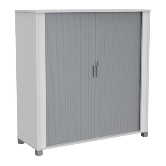
Summary of Contents for Knight Cubit Tambour
- Page 1 Cubit Tambour Assembly Instructions Tools Required: Powered Screwdriver knightgroup.co.nz...
-
Page 2: Setup And Installation
Cubit Tambour Assembly Instructions Thank you for purchasing Knight product, please carefully read the assembly instructions prior to installment to gain a complete understanding of the product. It provides you with important information about the safety, use, installation and maintenance. - Page 3 Cubit Tambour Assembly Instructions Parts Item Description Quantity Top Panel Left Side Panel (Outer) Left Side Panel (Inner) Incorrect Correct Right Side Panel (Outer) The turning direction of attaching Right Side Panel (Inner) Back Panel (Outer) Back Panel (Inner) Bottom Panel...
- Page 4 Cubit Tambour Assembly Instructions Parts Item Description Quantity 6x35 Cam Bolt 8x30 Dowel Pin Cam Sticker Shelf Pin 4x25 Screw Metal Feet 6x60 Fix Bolt c1 6x35 Cam Bolt d1 8x30 Dowel Pin c2 Cam Sticker s1 4x25 Screw p1 Shelf Pin...
- Page 5 Cubit Tambour Page 1 Page 1 Assembly Instructions Assembly Instructions Step 1 Preparation for top panel A, bottom panel G, vertical O, left side panel X, X1, right side panel Z, Z1, back panels D, D1. 1. Insert cams bolts (c1) and dowel pins (d1) into panels A, G, X, X1, Z and Z1 as illustrated above.
- Page 6 Cubit Tambour Page 2 Page 2 Assembly Instructions Assembly Instructions Step 2 Outer panel assembly - Back panel D, left side panel X, right side panel Z and batten O (Assemble with the top of back panel D pointing towards the floor). Insert cam bolts (c1) on panel X and Z into cams on panels D, O and tighten in a clockwise direction.
- Page 7 Cubit Tambour Page 3 Page 3 Assembly Instructions Assembly Instructions Step 3 Inner panel assembly - Back panel D1, left side panel X1, right side panel Z1. (Assemble with the top of back panel D1 pointing towards the floor). Insert cam bolts (c1) on panel X1 and Z1 into cams on panels D1 and tighten in a clockwise direction.
- Page 8 Cubit Tambour Page 4 Assembly Instructions Step 4 Top panel A assembly - Place top panel A on floor with tracking facing upwards. Insert cam bolts (c1) on panel A into cams on panels X, Z, D, O and tighten in a clockwise direction, repeat above assembly for the assembled inner panels X1, Z1 and D1.
- Page 9 Cubit Tambour Page 5 Page 5 Assembly Instructions Assembly Instructions Step 5 Door assembly - Insert and slide door sections onto main door panel with handle, repeat for second door. Place roller doors into groove of top panel A making sure all sections are sliding within the groove.
- Page 10 Cubit Tambour Page 6 Page 6 Assembly Instructions Assembly Instructions Step 6 Bottom panel G assembly - Insert cam bolts (c1) on panel G into cams on panels X, X1, D, D1, Z, Z1 & O (making sure tracking in panel G aligns with the bottom or the roller door), then tighten cams in a clockwise direction.
- Page 11 Cubit Tambour Page 7 Page 7 Assembly Instructions Assembly Instructions Step 7 Turn tambour over in to upright position. Moveable shelf E assembly - Insert shelf pins (p1) into panels D1, X1, and Z1 at desired shelf heights, place panel E on top of shelf pins (p1).
- Page 12 Cubit Tambour Page 8 Page 8 Assembly Instructions Assembly Instructions Complete knightgroup.co.nz...
Need help?
Do you have a question about the Cubit Tambour and is the answer not in the manual?
Questions and answers