
Related Manuals for ViewZ VZ-097RCR-D


Summary of Contents for ViewZ VZ-097RCR-D
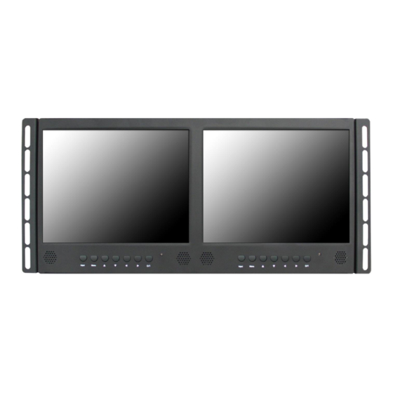
- Page 1 9.7-INCH RACK VALUE LED CCTV MONITOR USER MANUAL Please read this manual thoroughly before use, and keep it handy for future reference.
- Page 3 SAFETY INSTRUCTION ………………………………………………………….…… 2 ~ 3 CAUTIONS ……………………………………………………………......FCC RF INTERFERENCE STATEMENT ……………………………....... CONNECTING WITH EXTERNAL EQUIPMENT …………………………………… CONTROLS AND FUNCTIONS ……………………………………………………….. 7 ~ 14 MOUNTING GUIDE …………………………………………………………………….. D-SUB CONNECTOR PIN ASSIGNMENTS ………………………………………… POWER MANAGEMENT ……………………………………………………………… SPECIFICATIONS ……………………………………………………………………… TROUBLE SHOOTING GUIDE …………………………………………………..This Monitor was Manufactured by ISO 9001 Certified Factory...
- Page 4 Important Safety Instruction 1. Read these instructions. 2. Keep these Instructions. 3. Heed all warnings. 4. Follow all instructions. 5. Do not use this apparatus near water. 6. Clean only with dry cloth. 7. Do not block any ventilation openings. Install in accordance with the manufacturer’s instructions.
- Page 5 - The apparatus shall not be exposed to dripping or splashing and that no objects filled with liquids, such as vases, shall be placed no the apparatus. - Minimum distances(e.g. 10cm) around the apparatus for sufficient ventilation. “WARNING – To reduce the risk of fire or electric shock, do not expose the apparatus to rain or moisture.” “The apparatus shall not be exposed to dripping or splashing and no objects filled with liquids, such as vases, shall be placed on the apparatus.”...
- Page 6 CAUTION The power supply cord is used as the main disconnect device, ensure that the socket-outlet is located/installed near the equipment and is easily accessible. ATTENTIONN Le cordon d`alimentation est utillsé comme interrupteur général. La prise de courant doit être située ou installée à...
-
Page 7: Doc Compliance Notice
NOTE This equipment has been tested and found to comply with the limits for a Class A digital device, pursuant to Part 15 of the FCC Rules. These limits are designed to provide reasonable protection against harmful interference in a residential installation. This equipment generates, uses and can radiate radio frequency energy and, if not installed and used in accordance with the instructions, may cause harmful interference to radio communications. - Page 8 BACK 1. TRIGGER IN x(2) 2. AUDIO IN x(2) 3. VIDEO1(AV) IN (BNC Type) x(2) 4. VIDEO1(AV) OUT (BNC Type) x(2) 5. VIDEO2(AV) IN (RCA Type) x(2) 6. VIDEO2(AV) OUT (RCA Type) x(2) 7. VGA x(2) 8. DC 12V x(2) 6 …………………………………………….……………………………INSTRUCTION MANUAL...
-
Page 9: Power Led
FRONT 1. INPUT Selects VGA or AV inputs. Selects an option in the OSD. 2. MENU Activates or exits the OSD. Moves previous menu or status in the OSD. 3, 4. ▲ / ▼ Moves another option in the OSD. The ▼... - Page 10 OSD Menu Description All picture, sound settings and setup for the monitor can be adjusted in the OSD menu. (On Screen Display) To adjust the OSD screen: 1. Press the MENU button to enter the OSD menu. 2. Press the ▲/▼ buttons to select the desired option. The selected option is highlighted. 3.
- Page 11 B. SOUND Option Function Value VOLUME Adjust the level of audio volume. 0 ~ 100 MUTE Mutes speaker sound. Off or On INSTRUCTION MANUAL ………………………………………………………………………. 9...
- Page 12 C. PC (Only PC Mode) Option Function Value CONTRAST Adjusts intensity of the image. 0 ~ 100 BRIGHTNESS Adjusts brightness of the screen. 0 ~ 100 PC ADJUST Adjusts the PC Mode. See the table on Next page COLOR MODE Adjusts the vertically picture position.
-
Page 13: Color Mode
PC ADJUST Option Function Value AUTO ADJUST Auto geometry adjustment. H POSITION Adjusts the horizontally picture position. 0 ~ 100 V POSITION Adjusts the vertically picture position. 0 ~ 100 CLOCK Adjusts the vertical noise of screen image. 0 ~ 100 PHASE Adjusts the number of horizontal picture elements. - Page 14 D.SETUP Option Function Value English, German, French, Language Sets the language of the OSD menu. Italian, Spanish, Nederland and Korea Sets the OSD. See the table on Next page Key Lock Locks all buttons of the monitor. Off or On AV Mode: 16:9, 1:1, 4:3, 14:9, Zoom1, Sets the screen ratio.
-
Page 15: Trigger Time
Option Function Value H POSITION Move OSD horizontally on screen right or left. 0 ~ 100 V POSITION Move OSD vertically on screen up or down. 0 ~ 100 OSD TIMER Adjust OSD displaying time. 5 ~ 60 TRANSPARENT Adjust OSD transparent. Off or On TRIGGER Option... - Page 16 TRIGGER OPTION N/C(Normally Closed): The Trigger function is activated when the trigger cable is opened. N/O(Normally Opened): The Trigger function is activated when the trigger cable is closed. High: The Trigger function is activated when the trigger signal is DC 2~5[V]. Low: The Trigger function is activated when the trigger signal is DC 0~0.6[V].
- Page 17 Rack mount 465mm 187.5mm Rack Mounting Holes INSTRUCTION MANUAL ………………………………………………………………………. 15...
-
Page 18: Pin Assignments
▶ PIN ASSIGNMENTS Pin 1 RED VIDEO GREEN VIDEO SIGNAL CABLE DETECT BLUE VIDEO GROUND GROUND SDA(for DDC) GROUND H-SYNC.(or H+V SYNC.) RED GROUND V-SYNC. GREEN GROUND CL(for DDC) BLUE GROUND D-SUB ▶ ACCESSORY 1. Power adaptor x(2) 2. User’s manual 3. - Page 19 Power Consumption Mode Power Consumption Turned On < 16.4W Turned Off < 0.5W LED Indicator The power management feature of the monitor is comprised of three stages: Turned on(Green), No signal(AV mode: Green / VGA mode: Blinking green ) and Turned off(LED off).
-
Page 20: Input Signal
’’ Dual 9.7’’ Diagonal AM-TFT (Active-Matrix) Pixel pitch(mm) : 0.192(H) x 0.192(V) LED-Type ² Brightness: 350cd/m (Typical) Contrast Ratio: 600:1 (Typical) Response Time: 35msec (Typical) RESOLUTION 1024x768 @60Hz (H x V) HORIZONTAL : 31~48KHz, FREQUENCY VERTICAL : 56~60Hz VIDEO (BNC Type) x(2) (1ch input 1.0Vp-p, 75Ω... - Page 21 WEEE Symbols Correct Disposal of This Product (Waste Electrical & Electronic Equipment) (Applicable in the European Union and other European countries with separate collection systems) This marking shown on the product or its literature, indicates that it should not be disposed with other household wastes at the end of its working life.
- Page 22 MEMO...
- Page 24 L39ME0308 Rev.2...
Need help?
Do you have a question about the VZ-097RCR-D and is the answer not in the manual?
Questions and answers