
Subscribe to Our Youtube Channel
Related Manuals for Revolabs 10-FLX2-020-VOIP


Summary of Contents for Revolabs 10-FLX2-020-VOIP
- Page 1 REVOLABS FLX2 Wireless Conference System for Voice over IP System Guide Models: 10-FLX2-200-VOIP 10-FLX2-020-VOIP 10-FLX2-002-VOIP 10-FLX2-101-VOIP 10-FLX2-200-DUAL-VOIP...
- Page 2 © YAMAHA UNIFIED COMMUNICATIONS INC. All rights reserved. No part of this document may be reproduced in any form or by any means without express written permission from Yamaha Unified Communications, Inc. Product specifications are subject to change without notice.
-
Page 3: Safety Warnings
• Do not open the casings of any of the components of the FLX2 Conference Phone • Do not use any other accessories than Revolabs’ originals intended for use with this product. Use of non-original accessories may result in loss of performance, damage to the product, fire, electric shock or injury. -
Page 4: Table Of Contents
Contents Introduction ............................3 Safety Warnings ............................. 3 Contents ..............................4 General Information ..........................6 Quick setup for VoIP Conference Calls................... 7 Description ............................10 Unpacking ................................. 10 Installing FLX2 Components ......................11 FLX2 Base Station ............................11 FLX2 Charger Base ............................12 FLX Dialer ................................. - Page 5 System Information ............................41 Home .................................. 42 Call ..................................42 Setup ................................... 42 Web Interface ............................52 Enabling Web Access ............................ 52 Connecting to the FLX Web Interface...................... 52 Home Page ................................ 54 User Settings ..............................54 Administrator Settings ..........................58 Power On/Off the System Components ..................
-
Page 6: General Information
General Information The Revolabs FLX2 Conference Phone includes several components which, in the sum, make up the conferencing phone. The components are the Charger Base, Speaker, Microphones, and Dialer (handset). In addition, the Base Station receives the wireless signals from those components and... -
Page 7: Quick Setup For Voip Conference Calls
Quick setup for VoIP Conference Calls While all components delivered with the Revolabs FLX2 Conference Phone are partially charged, we recommend charging the Speaker, the Microphones, and the Dialer for at least 8 hours or overnight before starting to use the system. - Page 8 Phone configuration Before using the FLX for the first time, you will need to select the system language. The six options are English, Español (Spanish), Français (French), Deutsch (German), Italiano (Italian), and Português (Portuguese). Highlight the language of your choice, and press either “Enter”...
- Page 9 find the SIP settings under the Administrator tab on the top right. You will find the different SIP settings under SIP Registration, SIP Configuration, Transport, and Media. You have to press ‘Save’ an every page where you changed an entry to save these changes.
-
Page 10: Description
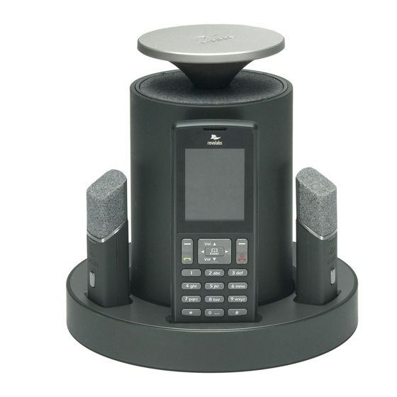
Conference phone mode. Description The Revolabs FLX2™ Wireless Conference Phone is a unique marriage of innovative technology and ergonomic design, allowing for an unparalleled experience when making telephone calls, video conference calls, or using it with your Bluetooth enabled cell phone or computer to make speaker phone calls. -
Page 11: Installing Flx2 Components
The Base Station is the wireless receiver and sender of the audio stream from the Microphones and to the Speaker, as well as to the Dialer. It features the ability to connect two Revolabs FLX Microphones and one Speaker wirelessly. The Base Station is designed to optimize audio and video conferencing by providing consistent audio input from all participants. -
Page 12: Flx2 Charger Base
FLX2 Charger Base The FLX2 Charger Base, shown below, provides charging capabilities for all battery operated system components, including the Dialer, the Speaker, and the Microphones, by allowing them to charge in one simple and organized location. The FLX2 Charger Base is not required while in a conference call, however it can maintain the charge of the FLX Speaker and FLX Dialer while a call is in progress. -
Page 13: Flx Dialer
FLX Dialer The FLX Dialer equips the user with an intuitive and interactive tool for configuring and operating the FLX System. The Dialer is not only used to make and answer conference calls, but it is also used for configuring the system settings, having a call using the handset, and monitoring the system components. -
Page 14: Flx Speaker
FLX Speaker The FLX Speaker, shown below, is a wireless active omnidirectional speaker that has been designed and optimized specifically for use with the FLX Conferencing System. The Speaker is equipped with a pairing button on the bottom and 4 LED indicators on the top to display the activity of the Speaker and the mute status of the system. -
Page 15: Flx Microphones
FLX Microphones The FLX Microphones provide a sleek and unobtrusive form factor allowing for closer proximity to the participants and creating the best audio available to the far end. They are equipped with a button for pairing and muting, an LED indicator to display mute status and battery charge level, and an internal buzzer to warn if the Microphones have lost connection to the Base Station. -
Page 16: Voip Configuration
Initial Setup After unpacking the FLX2 Conferencing System, there are a few initial setup tasks that must be performed before a call can take place or any system configuration can be changed. Connecting System Cables The FLX2 Charger Base has a power supply that needs to be connected, as shown below. - Page 17 will also have to enable the extension (user) you want to use with the FLX on your PBX. Please review your PBX documentation on information on how to do that. From the FLX Handset Depending on your IP PBX, different settings will be required for your FLX to work in your environment.
-
Page 18: Managing A Call
Note: For some of the common IP PBXs, Yamaha Unified Communications provides documents on required settings for the FLX. The documents can be found on the support website at www.uc.yamaha.com Managing A Call The FLX2 Wireless Conferencing system is equipped with a VoIP interface that allows the system to make conference calls in a VoIP network. -
Page 19: Flx Home Screen
‘speaker mode’ only. A Bluetooth call is controlled by the connected Bluetooth device. A Bluetooth call can be made at the same time as a video call. NOTE: Revolabs FLX only supports the Hands Free Profile (HFP) for Bluetooth 2.0 or higher. Applications that try to use... - Page 20 or the speaker is switched off, and a yellow speaker means that the status of the speaker is unknown, e.g. it was taken out of range or connection was unexpectedly lost. A green microphone indicates that the microphone is available and unmuted, a red indicates it is available but muted, grey indicates it is switched off, and yellow means the current status is unknown, e.g.
-
Page 21: Placing A Voip Call
Placing a VoIP Call 1. From the home screen on the FLX Dialer enter the phone number to be called. 2. Once the number is entered completely, press the green ‘call’ button to initiate the phone call. 3. If any Microphones are out of the Charger Base and active, the call will default to ‘speaker mode’... -
Page 22: Declining An Incoming Voip Call
NOTE: If there is either no Speaker active or no Microphones outside the Charger Base when the incoming call is answered from the FLX Dialer, the call will default to ‘handset mode’ and will remain in ‘handset mode’. call can only be switched to ‘speaker mode’ if the speaker and at least one microphone is switched on. -
Page 23: Ending A Telephone Call
Ending a Telephone call 1. A call can be ended in two fashions. a. Press the Red ‘End Call’ button on the FLX Dialer during a call. b. Place the Dialer in the charger. (‘Handset mode’ only) 2. When a call is ended the home screen is shown again. - Page 24 Muting a Call 1. In handset mode, the ‘Mute’ and ‘UnMute’ key will mute/unmute the FLX Dialer microphone, not the wireless Microphones. 2. In speaker mode, the ‘Mute’ and ‘UnMute’ key will mute/unmute all wireless Microphones. NOTE: If the setting ‘All Mic Mute’ is OFF, the Microphone mute buttons will be locked while the Master Mute is active.
- Page 25 Conference Call There are two ways to start a conference call: 1. Press the ‘Enter’ key to access the Active Call Menu and select ‘Conference’. 2. Create the second call by selecting Dialer, Contacts, or Recent. 3. Initiate the second call. 4.
-
Page 26: Component Behavior In And Out Of The Charger Base
Component behavior in and out of the Charger Base Each system component will respond differently when placed in or out of the charger during an active telephone call. The following is a description of what can be expected. Dialer When the Dialer is placed into the Charger Base during a call in ‘speaker mode’, the call will not be affected and the Dialer will enter its charging mode. -
Page 27: Bluetooth
Bluetooth The FLX2 System is equipped with a Bluetooth interface allowing a call to be placed through a cell phone, computer, or 3 party Bluetooth device. The FLX Microphones and Speaker then act as the Microphone and Speaker for that call. The FLX2 System only supports the Hands Free Profile for Bluetooth 2.0 or newer. - Page 28 Adding a Device 1. Go to the Menu Bluetooth. Select ‘Discovery Mode’ to activate Bluetooth and accept Bluetooth Request from other devices. 2. The FLX Dialer displays “This device is visible to other devices in range for 3 minutes” 3. The discovery mode screen will read “System in discoverable Mode, Start Scan From BT Device.
- Page 29 Viewing Device Details 1. Go to the Menu Bluetooth. Select ‘Device List’. 2. Select desired device and press the ‘Enter’ key or the ‘Select’ key to view device details 3. Device Information screen is shown with device name, address, BT version, and date/time the device was first connected.
-
Page 30: Making A Call Via Bluetooth
Setting Device Trust Level 1. Go to the Menu Bluetooth. Select ‘Device List’. 2. Select the desired device and press the ‘Enter’ key or the ‘Select’ key to view the device details. 3. Press the ‘Option’ key and then select ‘Options…’. 4. -
Page 31: Video Conference Collaboration
Video Conference Collaboration The FLX2 System is equipped with balanced analog audio input and output to be connected to 3 party video or PC conferencing system. This allows the FLX Microphones and Speaker to be used as Microphones and Speaker for video calls. It also provides Acoustic Echo Cancelation and Noise Control to the video call. -
Page 32: Mixing The Audio Signals
Mixing the audio signals As discussed earlier, Audio and Video, or Bluetooth and Video calls can be made simultaneously from a FLX system, requiring FLX to mix the audio of the different inputs to go to the different outputs. In the Audio Controls menu, available from the main menu and the Active Call Menu, the Audio Mixer menu is offered. -
Page 33: Flx2 System Configuration
FLX2 System Configuration There are many features to the FLX2 System that can be modified and configured using the FLX Dialer. The following is a list of those features and their options. Menu Hierarchy Device Audio System Recent Bluetooth Home Call Contacts Setup... -
Page 34: Recent Calls
Recent Calls The Recent Calls call log stores the contact information from calls placed or received, allowing the user to review recent calls, redial a recent call, or store a recent call in the system directory. Recent Call Log 1. Access recent call log by browsing: Menu Recent Calls 2. - Page 35 View Recent Call Information 1. Access the recent call log by browsing: Menu Recent Calls or pressing the green ‘Call’ button while no call is in progress. 2. You can view a recent call one of two ways: a. In the recent call list, select the entry you want to view, and press the ‘View’...
-
Page 36: Contacts
Delete Call History 1. Access the recent call log by browsing: Menu Recent Calls or pressing the green ‘Call’ button while no call is in progress. 2. In the Recent Call menu, press ‘Enter’ to open the Options Menu. 3. - Page 37 Edit a Contact 1. Browse to the Contacts menu: Menu Contacts, scroll to the desired contact, and select ‘View’ to access the contact. 2. The contact screen shows the current name and number. Pressing the ‘Edit’ key will open the Edit Contact menu.
- Page 38 Search for Contact 1. Browse to the Contacts menu: Menu Contacts. 2. Use the alphanumeric keys to apply a filter a. Once a key is pressed the title line will read ’Contact()’ and display the characters being typed. b. The search string can be up to 5 characters long.
-
Page 39: Audio Control
Set Speed Dial 1. Browse to the Contacts menu: Menu Contacts, scroll to the desired contact, and press the ‘View’ key to access the contact. 2. The contact view screen shows the current name and number. Pressing the ’Edit’ key will open the Edit Contact menu. - Page 40 Ringer 1. Browse to the Ringer menu: Menu Audio Controls Ringer. 2. Choose ‘Ringer Volume’ in the Ringer Settings menu to adjust the Ringer Volume. 3. Press the up and down buttons to increase and decrease the volume. 4.
-
Page 41: Device Status
played once a phone calls ends, reminding users to return the components – microphones, speaker, and dialer – to the charger tray. Highlight the option and press “Select” or “Enter” to toggle between the ON and OFF mode. Device Status 1. -
Page 42: Home
Bluetooth The ‘Bluetooth’ menu has been explained earlier in this manual on page 27. Home When selecting the ‘Home’ menu item, the Dialer will go back to displaying the home screen. The same effect can be achieved by pressing the ‘Return’ key, or the red ‘End Call’... - Page 43 Date/Time 1. Browse to the Date/Time menu: Menu Setup Set Date/Time. 2. To set the date or time, select either the ‘Set Date’, or ‘Set Time’ option, and press either ‘Enter’ or ‘Select’. 3. Edit time and date (month/day/year) using the numeric keys and the left and right buttons.
- Page 44 4. To set the time before the call is forwarded to the ‘No Answer’ number, select ‘No Answer Delay’ and set the time in seconds. Advanced Setup The following is a list of advanced configuration settings that are protected by a 4 digit password for administrator access only.
- Page 45 Aux Audio ‘Aux Audio’ is to control the AUX In and AUX Out connectors on the base. Aux In ON/OFF and Aux Out ON/OFF allow enabling / disabling the Aux connectors of the FLX phone. Aux In Level allows changing the level of the Aux In signal.
- Page 46 Admin Settings The Admin Settings menu allows changing settings that are related to general system settings. Setting System Name 1. Go to Menu Setup Advanced Setup Admin Settings Set System Name. 2. Change the current System Name to the new name, and press Enter.
- Page 47 you switch Recent Calls OFF the list of the recent calls will be erased and no future information on recent calls will be kept in the system. Web Access ON / OFF Web Access OFF allows you to disable the web interface into the FLX. If Web Access is set to off, any attempt to open the web interface will be declined.
- Page 48 of the Speaker until you hear the Speaker shut-off or the LEDs turn off. 2. Ensure that the Base Station is plugged in and powered up. 3. On the Dialer, browse to the Pairing menu: Menu Setup Advanced Setup Pairing.
- Page 49 Network Settings 1. Browse to the Network Settings menu: Menu Setup Advanced Setup Network Settings. a. You can change the DHCP configuration by turning it off and manually setting your IP address in the IP Settings. If DHCP is set to ON this takes precedent over static IP settings.
- Page 50 be used. Please note that your IP PBX might override the Display name sent by the FLX and replace it with names configured in the PBX. iv. ‘Username’ is the extension off the IP PBX this phone will be reached under v.
-
Page 51: Web Interface
selecting the local Country or region. Please ensure that this selection is always set to your local country or region. Changing this setting might lead to loss of connectivity to the microphones and speakers. If your microphones and speakers do not automatically reconnect after changing the Region setting, you need to pair all of them again to your system. -
Page 52: Enabling Web Access
Enabling Web Access To enable the web interface, from the FLX Handset select Menu > Setup > Advanced Setup, enter the administrator password, then select Admin Settings > Web Access ON/OFF. Press the Enter button to toggle between ON and OFF to control access. Factory default is web access enabled. -
Page 53: Home Page
Home Page The Home page shows general information about the system as shown below. The Product field is a brief description of the FLX phone to which you are connected. The System IP Address shows the IP address of the device, whether it was configured by DHCP or with a static IP address. - Page 54 Audio The Audio page can be used to configure audio settings and audio mixer settings of your FLX. These settings are also available on the Handset. The figure below shows the Audio page, followed by a description of each setting. After changing any of the settings, click Save to save the settings.
- Page 55 the phone audio received from the far end while in a call. It is a sliding scale from -8 (favoring microphones) to +8 (favoring phone). Call Forwarding The Call Forwarding settings are used to forward incoming calls to another phone. There are three conditions that can be set to determine when to forward calls, as shown in the figure below.
- Page 56 Date/Time Network Time To enable the system to automatically detect the local date and time by using a public Date Time Server (DTS), set the Network Time to On. If you want to manually specify the local date and time, choose Off.
-
Page 57: Administrator Settings
Restarting the Phone To restart the phone, choose Restart from the User menu or Administrator menu on the left of the page. On the Restart page click the Restart button as shown below. The page will indicate that the system is restarting. After the phone has restarted, choose the web browser’s refresh option to refresh the web session. - Page 58 Network Settings Use the Network Settings page to specify how IP addressing is to be determined for the phone connected to the IP network. You can use DHCP to automatically detect the phone’s IP address and network server settings, or you can manually specify a static IP address for the phone and the network server addresses provided by your network administrator.
- Page 59 Network Settings Connection Type Select the network connection type, either DHCP or Static IP. If you choose Static IP, specify the Static IP Address, Subnet Mask, and Default Gateway in the fields below. Static IP Settings Static IP Address The Static IP Address is the IP address that the network administrator has assigned to the phone.
- Page 60 SIP Registration The SIP Registration page is used to configure the SIP registrar and proxy settings and the SIP account and user settings for the phone. The minimum number of information required to register your phone is the Registrar, the Username and Password. If ID and Display Name are not set, FLX will use the user name for both of these parameters.
- Page 61 When this field is specified, the phone will register with the primary SIP registrar (The “Registrar” field) if it is accessible. If the primary SIP registrar becomes inaccessible via UDP or TCP, the phone will attempt to register with the backup registrar. If the phone successfully registered with backup registrar, it will switch to the backup registrar to perform outgoing calls and receive incoming calls.
- Page 62 SIP Settings Use the SIP Settings page to configure settings related to SIP sessions, as shown in the illustration below. After changing any of these settings, the phone must be restarted for the changes to take effect. SIP Settings Use SIP session Specify the preference for using SIP session keep-alive timers.
- Page 63 expiration period the SIP session timed out if it does not receive a refresh message from the remote phone. It is measured in seconds; the default is 1800. At call negotiation, the nodes will negotiate the expiration period to be used for the session. Session timers This is the minimum session timer expiration period that FLX will minimum...
- Page 64 in their short forms to reduce size. By default, the option is not enabled and SIP headers in outgoing messages will be encoded in their full names. (See SIP protocol standard, IETF RFC 3261.) DTMF Signaling Select the signaling method for transmitting DTFM tones, either via Method RTP (RFC2833) or SIP INFO messages.
- Page 65 Transport Use the web interface’s Transport page to manage transport and Network Address Translation (NAT) settings, and to enable or disable Quality of Service (QoS). The illustration below shows the Transport page. After changing any of these settings, the phone must be restarted for the changes to take effect.
- Page 66 Transport Settings Use SRTP Use this setting to control Secure Real-time Transport Protocol (SRTP) usage. These are the available options: Disabled – Do not use SRTP; always use RTP. This is the default setting. Optional – Use the optional disposition for SRTP in SDP. If the remote end supports SRTP, then use SRTP;...
- Page 67 remote nodes), FLX sends STUN binding requests as part of the media connectivity tests. When a candidate is nominated for use, a STUN binding request is sent with a flag indicating that the candidate pair is nominated. There are two nomination methods that can be used: Regular –...
- Page 68 Differentiated Services Code Point (DSCP) in the IP header is set to 24 (0x18). For layer 2, IEEE 802.1p tagging is supported. This option is unchecked by default. Media Settings Use the Media page to specify the preferred audio codecs and other audio stream processing preferences as shown in the illustration below.
- Page 69 Disable silence Select this option to disable silence detector/voice activity detector detector/voice (VAD). VAD is a technique used in audio processing to detect the activity detector presence or absence of human speech. Disabling VAD is sometimes useful to work around NAT problems. This option is unchecked by default.
- Page 70 Advanced Audio Settings Use the Advanced Audio Settings page to specify microphone mute behavior, AUX audio in and out settings, and Acoustic Echo Cancellation (AEC) settings. The illustration below shows this page. The settings and options on this page reflect the same settings as can be done on the handset, allowing remotely setting and managing the phone behavior.
- Page 71 RF Setting Use the RF Setting page to set the Radio Frequency (RF) signal strength of the base station and microphones. There are two RF Power settings: High or Low. The default is High. Low can be selected to reduce the signal strength. Lower signal strength reduces the maximum distance between the base station and any of the wireless devices.
- Page 72 Enabled web interface. If access is enabled, users can browse to the FLX using a web browser. Even if enabled, the web interface is password protected for all pages. It is restricted to Administrator use. If disabled, any web-access is rejected. Once web access is disabled, it can only be enabled again by an administrator from the handset.
- Page 73 To export FLX configuration settings, click the Export button. A File Download window will appear prompting you to open or save the file as shown below. Click the “Save” button to save the file to the desired location. To import a configuration file, open a web session and login to the target phone to be configured, and select the Administrator >...
- Page 74 Select the Administrator > System Log page, and click the Retrieve button to begin the download process as shown in the picture. Your web browser should indicate the download progress. When the download is complete, you will be prompted to save the compressed configuration file. The file name will include the IP address of the FLX and a date and time stamp, for example, log- 10.134.123.101-120131-210112.tar.gz.
-
Page 75: Power On/Off The System Components
Call Status The Call Status page displays summary call statistics while in an active call. If there is no active call, the page will show a “No active call” message. If in a call, the page will show stats similar to those below. Click the Refresh button to manually refresh the page. - Page 76 To power the Speaker back on, either: 1. Hold down the button on the bottom of the Speaker until the LED indicators on the top of the Speaker turn green. Once the LED indicators turn green, release the button and the Speaker will power on and connect to the system. 2.
-
Page 77: Battery Exchange
Battery Exchange The rechargeable batteries in the different FLX components can all be exchanged. Please note that only Yamaha Unified Communications approved batteries should be used for the replacement. The following sections explain how to change the batteries in the different components. We recommend charging any component for 8 hours after exchanging the battery. -
Page 78: Microphones
Microphones To exchange a microphone battery push the bottom part of the back cover slightly down towards the charger port and then lift it as shown in the illustration below. Carefully take the battery out of the plastic cover. Put the new battery into the back cover as shown in the figure below. -
Page 79: Speaker
Speaker To change the rechargeable battery in the FLX speaker you will need to use a screwdriver to loosen the screw on the bottom of the speaker. Once the screw is loose, the bottom door of the speaker will open, revealing the rechargeable battery pack. -
Page 80: Connecting Using Aux In / Aux Out
The following table shows the different cables required to connect the FLX to common Connecting using AUX IN / AUX OUT videoconferencing codecs in the market. FLX OUT Brand Codec Connects FLX IN Level Cable Connects TO: Cable Lifesize Mic Input 07-35MUTO35MU-01 Line Output 07-35MUTO35MS-01... -
Page 81: Troubleshooting
KX-VC300 Line 07-35MUTODRCA-01 Line Output 07-35MUTODRCA-01 To connect a FLX to a computer we recommend using Revolabs’ USB connector kit, 01-USBAUD35-KIT. This kit includes a USB audio dongle and two cables to connect to the FLX. Troubleshooting Warning Messages Speaker / Microphone Link Lost If a FLX Microphone or FLX Speaker loses connection to the FLX2 Base Station, the LED indicator will begin flashing a sequence of red –... -
Page 82: Microphone, Speaker, Or Dialer Not Connecting To Base Station
Dialer Low Battery When the Dialer experiences a low battery it will display a ‘low battery’ notification on the screen. The Dialer should be returned to the charger until the battery status on the home screen shows a full charge. Dialer Link Lost If the FLX Dialer loses connection to the FLX2 Base Station it will display a ‘connection lost’... -
Page 83: Microphone, Speaker, Or Dialer Not Paired With Base Station
Microphone, Speaker, or Dialer not paired with Base Station Please follow the descriptions on page 42 on how to pair the different components with the Base Station. LED Indicators Device LED Indicator Status Microphone in Charger Base Steady Red Charging Steady Green Fully charged Active phone call, both microphones in Charger... - Page 84 Device LED Indicator Status still be individually muted o Connected, battery charging, no phone call in progress, Microphone(s) outside of the Charger Base unmuted o Connected, battery charging, phone call in progress, Master Mute or “All Mic Mute” is ON, all Microphones are muted Steady Red o Connected, battery charging, no phone call in...
-
Page 85: Reset To Factory Defaults
Technical Specifications Models The Revolabs FLX2 VoIP System is available with a variety of configurations to provide the best audio capture in the industry. The following is a list of the available models. All of these models are SIP enabled and require an IP connection. - Page 86 Wireless Technology DECT DECT 6.0 for US, ETSI ETS 300 175 for other countries Bluetooth BT 2.1 + EDR Wireless Range DECT 65 feet, 20 meters Bluetooth Class II, 33 feet, 10 meters Security (DECT / Bluetooth) DECT: 128 bit encryption Noise Cancelation Noise cancellation on the Microphone Echo Cancelation...
- Page 87 Dialer Dimensions Dialer 125 x 48 x 11mm Weight 67.5g Microphone and Speaker 300 – 3300Hz bandwidth Battery life 8 hours Charge time 3 hours Display High resolution color LCD display Caller ID Support for multiple Caller ID standards Phonebook Up to 100 entries Keypad 12 key telephone keypad...
-
Page 88: Regulatory Information
Regulatory Information FCC Notice to Users This device complies with Part 15 of the FCC Rules. Operation is subject to the following two conditions: (1) this device may not cause harmful interference, and (2) this device must accept any interference received, including interference that may cause undesired operation. Users are not permitted to make changes or modify the equipment in any way. -
Page 89: Industry Canada Notice To Users
Industry Canada Notice to Users This Class B digital apparatus complies with Canadian ICES-003. Operation is subject to the following two conditions: (1) This device may not cause interference and (2) This device must accept any interference, including interference that may cause undesired operation of the device Model Number Industry Canada Identification... -
Page 90: Restricted Use With Certain Medical Devices
Restricted use with certain medical devices Hearing Aids Some devices may interfere with some hearing aids. In the event of such interference, you may want to consult with your hearing aid manufacturer to discuss alternatives. Other Medical Devices If you use any other personal medical device, consult the manufacturer of your device to determine if it is adequately shielded from RF energy. - Page 91 According to the requirement of the WEEE legislation the following user information is provided to customers for all branded Revolabs products subject to the WEEE directive. “The symbol on the product or its packaging indicates that this product must not be disposed of with your other household waste.
-
Page 92: Limited Warranty And Limitation Of Liability
Limited Warranty and Limitation of Liability Limited Warranty Yamaha Unified Communications warrants to the end user the outside of the shipping container and the serial number (“Customer”) and model of the returned product must match the RMA. that this product will be free from significant defects in Products returned without a RMA number will be returned to workmanship and materials, under normal use and service, for the customer. - Page 93 TO THE FULL EXTENT ALLOWED BY LAW, YAMAHA UNIFIED COMMUNICATIONS EXCLUDES FOR ITSELF AND 1TS SUPPLIERS ANY LIABILITY, WHETHER BASED IN CONTRACT OR TORT (INCLUDING NEGLIGENCE), FOR INCIDENTAL, CONSEQUENTIAL, INDIRECT, SPECIAL, OR PUNITIVE DAMAGES OF ANY KIND, OR FOR LOSS OF REVENUE OR PROFITS, LOSS OF BUSINESS, LOSS OF INFORMATION OR DATA, OR OTHER FINANCIAL LOSS ARISING OUT OF OR IN CONNECTION WITH THE SALE, INSTALLATION, MAINTENANCE, USE, PERFORMANCE, FAILURE, OR INTERRUPTION OF ITS PRODUCTS, EVEN IF YAMAHA UNIFIED COMMUNICATIONS OR ITS...
-
Page 94: Gpl Licensed Software
GPL LICENSED SOFTWARE The following GPL licensed software is used in this product and is subject to the GNU General Public License version 2 (GPLv2) License Agreements included as part of this documentation: uClinux 2.6.26 BusyBox 1.2.2 Source code for this software can be obtained by contacting Yamaha Unified Communications, Inc. - Page 95 Finally, any free program is threatened constantly by software patents. We wish to avoid the danger that redistributors of a free program will individually obtain patent licenses, in effect making the program proprietary. To prevent this, we have made it clear that any patent must be licensed for everyone's free use or not licensed at all.
- Page 96 based on the Program is not required to print an announcement.) These requirements apply to the modified work as a whole. If identifiable sections of that work are not derived from the Program, and can be reasonably considered independent and separate works in themselves, then this License, and its terms, do not apply to those sections when you distribute them as separate works.
- Page 97 If distribution of executable or object code is made by offering access to copy from a designated place, then offering equivalent access to copy the source code from the same place counts as distribution of the source code, even though third parties are not compelled to copy the source along with the object code.
- Page 98 willing to distribute software through any other system and a licensee cannot impose that choice. This section is intended to make thoroughly clear what is believed to be a consequence of the rest of this License. 8. If the distribution and/or use of the Program is restricted in certain countries either by patents or by copyrighted interfaces, the original copyright holder who places the Program under this License may add an explicit geographical distribution limitation excluding those countries, so that distribution is permitted only in or among countries...
- Page 99 NO WARRANTY 11. BECAUSE THE PROGRAM IS LICENSED FREE OF CHARGE, THERE IS NO WARRANTY FOR THE PROGRAM, TO THE EXTENT PERMITTED BY APPLICABLE LAW. EXCEPT WHEN OTHERWISE STATED IN WRITING THE COPYRIGHT HOLDERS AND/OR OTHER PARTIES PROVIDE THE PROGRAM "AS IS" WITHOUT WARRANTY OF ANY KIND, EITHER EXPRESSED OR IMPLIED, INCLUDING, BUT NOT LIMITED TO, THE IMPLIED WARRANTIES OF MERCHANTABILITY AND FITNESS FOR A PARTICULAR PURPOSE.
-
Page 100: Technical Support
Technical Support If you are experiencing technical problems or if you have questions about the operation, configuration or troubleshooting of any Revolabs product, please email uc-support@music.yamaha.com or call +1-800-326-1088 MN-FLX2-VOIP-SYT-GUIDE-20180521-EN Copyright 2018 Yamaha Unified Communications, Inc.
Need help?
Do you have a question about the 10-FLX2-020-VOIP and is the answer not in the manual?
Questions and answers