
Subscribe to Our Youtube Channel
Related Manuals for Dalsa P4-CC-04K07T


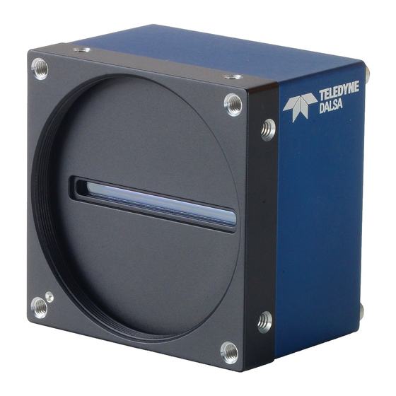
Summary of Contents for Dalsa P4-CC-04K07T
- Page 1 Piranha4 Color P4-CC-04K07T-00-R Camera User’s Manual 03-032-20180-00 www.teledynedalsa.com...
- Page 2 Piranha4 4K Camera Color User's Manual © 2013 Teled yne DALSA, Inc. All inform ation provid ed in this m anual is believed to be accurate and reliable. No responsibility is assum ed by Teled yne DALSA for its use. Teled yne DALSA reserves the right to make changes to this inform ation w ithout notice.
-
Page 3: Table Of Contents
Step 3. Establish Communication with the Camera ......................32 Power on the camera ............................32 Connect to the frame grabber ......................... 32 Connect to the camera ............................ 32 Check LED Status ............................33 Software Interface ............................33 Using Sapera CamExpert with Piranha4 Cameras ......................34 Teledyne DALSA 03-032-20180-00... - Page 4 Transport Layer Feature Descriptions ......................79 Acquisition and Transfer Control Category ........................80 Acquisition and Transfer Control Feature Descriptions................... 80 Serial Port Control Category .............................. 81 Serial Port Control Feature Descriptions ......................81 File Access Control Category .............................. 82 03-032-20180-00 Teledyne DALSA...
- Page 5 A simple workaround accomplishes this ......................109 Sample Code ..............................110 Appendix F: Camera, Frame Grabber Communication _______________________________________________________ 111 Setting Up Communication between the Camera and the Frame Grabber ............ 111 EMC Declaration _________________________________________________________________________________ 113 Revision History _________________________________________________________________________________ 114 Index ________________________________________________________________________________________ 115 Teledyne DALSA 03-032-20180-00...
-
Page 6: System Precautions
Ad d itional inform ation on cleaning the sensor w ind ow and p rotecting it against d u st, oi l, blem ishes, and scratches can be fou nd here, Ap p end ix D: The Sensor Wind ow 03-032-20180-00 Teledyne DALSA... -
Page 7: The Piranha4 Color Camera
Camera Highlights Based on Teled yne DALSA's u niqu e CMOS color line scan sensor architectu re, the new Piranha4 4k Trilinear color cam era p rovid es ou tstand ing signal-to-noise p erform ance for high sp eed im aging. The P4- 4k has 4k resolu tion w ith a 10 µm x 10 µm p ixel size for op tim ized op tical d esign. -
Page 8: Camera Performance Specifications
The cam era is available in the follow ing configu rations: Table 1: Camera Models Overview Model Number Description P4-CC-04K07T-00-R 4k resolution, 70 kH z line rate, Cam era Link interface. Table 2: Software Software Product Number / Version Number... -
Page 9: Certifications
Piranha4 4K Color Camera User's Manual *N ote: The P4-CC-04K07T-00-R cam era has been d esigned to ou tp u t 4096 p ixels of RGB d ata. H ow ever, d u e to a lim itation of the sensor, the ou tp u t is lim ited to 4080 p ixels for the cam era ‘s initial release. Th is restriction w ill be resolved in a fu tu re release. -
Page 10: Sensor Responsivity And Design
. To p revent infrared from d istorting the im ages you scan, u se an IR cu t off filter su ch as a BG-38 on the lens. 03-032-20180-00 Teledyne DALSA... - Page 11 Piranha4 4K Color Camera User's Manual 0.18 P4 White LED Calibration Source Relative Intensity vs Wavelength 0.16 0.14 0.12 [ADD GRAPH ] 0.08 0.06 0.04 0.02 Wavelength (nm) Figure 2: Calibration Source Relative Intensity vs. Wavelength Teledyne DALSA 03-032-20180-00...
-
Page 12: Spatial Correction And Trilinear Sensor Design
Spatial Correction and Trilinear Sensor Design The P4-CC-04K07T-00-R cam era u ses a trilinear sensor w here three sep arate 4K lines of p ixels are u sed — one for red , the center for blu e and the last for green. - Page 13 Line Sp atial Correction = 4.3 (ssa = 4.3) Example 3. Target running faster than example 1. same EXSYNC (trigger) frequency Line Sp atial Correction = 3 (ssa = 3) Line Sp atial Correction = 1.73 (ssa = 1.73) Teledyne DALSA 03-032-20180-00...
- Page 14 Line Sp atial Correction = 3 (ssa = 3) Line Sp atial Correction = 1 (ssa = 1) Example 5. Target running faster than EXSYNC Line Sp atial Correction = 3 (ssa = 3) Line Sp atial Correction = 5 (ssa = 5) 03-032-20180-00 Teledyne DALSA...
-
Page 15: Camera Direction
―u p sid e d ow n‖. Note: The exam p le here assu m es the u se of a lens (w hich inverts the im ag e). Figure 4: Object Movement and Camera Direction Example, with a Lens Teledyne DALSA 03-032-20180-00... -
Page 16: Mechanicals
HARMONY SURFACE FINISH PROPRIETARY THIS DOCUMENT AND THE INFORMATION IT CONTAINS ARE PROPRIETARY TO TELEDYNE DALSA INC.. THIS DOCUMENT MUST NOT BE DUPLICATED, OR ITS CONTENT USED OR DISCLOSED (IN WHOLE OR IN PART) WITHOUT PERMISSION FROM TELEDYNE DALSA INC. - Page 17 Figure 7: Piranha4 Heat Sink Accessories Kit Optional Lens Mount and Heat Sink Accessories Part No. Description AC-LN -00002-A0-R M58 to F-m ount ad apter (12m m BFD), heavy d uty AC-MS-00108-00-R H eat sink for P4-4k/ 2k cam eras Teledyne DALSA 03-032-20180-00...
-
Page 18: Camera Mounting And Heat Sink Considerations
Teled yne DALSA recognises that each cu stom er‘s ap p lication can be u niqu e. In consid eration, the P4 cam era heat sinks have been d esigned in su ch a w ay that they can be rep ositioned on the d ifferent faces of the cam era or rem oved entirely, d ep end ing on the m ou nting configu ration and its heat sinking p otential. -
Page 19: Quick, Simple Steps To Acquire An Image
Ap p end ix C: Qu ick Setu p and Im age Acqu isition Teledyne DALSA 03-032-20180-00... -
Page 20: Software And Hardware Setup
4. Operate the Camera At this p oint you w ill be read y to start op erating the cam era in ord er to acqu ire im ages, set cam era fu nctions, and save settings. 03-032-20180-00 Teledyne DALSA... -
Page 21: Step 1. Install And Configure The Frame Grabber And Software
The Cam era link XML d evice d escrip tion file is em bed d ed w ithin the cam era firm w are allow ing Cam era link-com p liant ap p lications to recognize the cam eras‘ cap abilities im m e d iately after connection. Teledyne DALSA 03-032-20180-00... -
Page 22: Step 2. Connect Data, Trigger, And Power Cables
Static electricity can d am age electronic com p onents. It‘s critical that you d ischarge any static electrical charge by tou ching a grou nd ed su rface, su ch as the m etal com p u ter chassis, b efore hand ling the cam era hard w are. 03-032-20180-00 Teledyne DALSA... -
Page 23: Data Connector: Camera Link
For d etailed inform ation on Cam era Link p lease refer to the Cam era Link Road Map available from the Know led ge Center on the Teled yne DALSA Web site. Figure 9. SDR26 Camera Link Connector Data 2... -
Page 24: Camera Timing
Piranha4 4K Camera Color User's Manual Direction Spare Table 4: Camera Control Configuration For ad d itional Cam era Link d ocu m entation refer to the Teled yne DALSA Web site‘s Know led ge Center ap p lication notes. - Page 25 The RGB ou tp u t form at is com p atible w ith the Cam era Link sp ecification for Med iu m RGB. Line rates u p to 70 kH z can be achieved by u sing the Area of Interest (AOI) featu re; w here the sm aller the AOI, the greater the p otential line rate. Teledyne DALSA 03-032-20180-00...
- Page 26 RGB d ata from the fram e grabber bu ffer by the host ap p lication. Line rates u p to 70 kH z can be achieved by u sing the Area of Interest (AOI) featu re; w here the sm aller the AOI, the greater the p otential line rate. 03-032-20180-00 Teledyne DALSA...
- Page 27 RGB d ata from the fram e grabber bu ffer by the host ap p lication. Line rates u p to 70 kH z can be achieved by u sing the Area of Interest (AOI) featu re; w here the sm aller the AOI, the greater the p otential line rate. Teledyne DALSA 03-032-20180-00...
- Page 28 The RGB ou tp u t form at is com p atible w ith the Cam era Link sp ecification for Med iu m RGB. Line rates u p to 70 kH z can be achieved by u sing the Area of Interest (AOI) featu re; w here the sm aller the AOI, the greater the p otential line rate. 03-032-20180-00 Teledyne DALSA...
- Page 29 The RGB ou tp u t form at is com p atible w ith the Cam era Link sp ecification for Med iu m RGB. Line rates u p to 70 kH z can be achieved by u sing the Area of Interest (AOI) featu re; w here the sm aller the AOI, the greater the p otential line rate. Teledyne DALSA 03-032-20180-00...
-
Page 30: Camera Link Cable Quality And Length
Input Signals, Camera Link The cam era accep ts control inp u ts throu gh the Cam era Link SDR26F connector. The cam era ship s in internal sync, and internally p rogram m ed integration . EXSYNC (Exposure Start) 03-032-20180-00 Teledyne DALSA... -
Page 31: Output Signals, Camera Link Clocking Signals
The cam era requ ires a single voltage inp u t +12 VDC to +24 VDC. The cam era m eets all p erform ance sp ecifications u sing stand ard sw itching p ow er su p p lies, althou gh w ell-regu lated linear su p p lies p rovid e op tim u m p erform ance. Teledyne DALSA 03-032-20180-00... -
Page 32: Leds
In the Devices list area on the left sid e, select the COM p ort below the Cam era Link label. 03-032-20180-00 Teledyne DALSA... -
Page 33: Check Led Status
All the cam era featu res can be controlled throu gh the Cam Exp ert interface. For exam p le, u nd er the Sensor Control m enu in the cam era w ind ow you can control the line rate and exp osu re tim es. Teledyne DALSA 03-032-20180-00... -
Page 34: Using Sapera Camexpert With Piranha4 Cameras
Note: The availability of the featu res is d ep end ent on the Cam Exp ert u ser setting. A note on the CamExpert examples show n here: The examples show n for illustrative purposes and may not entirely reflect the features and parameters available from the camera model used in your application. 03-032-20180-00 Teledyne DALSA... -
Page 35: Camexpert Panes
Piranha4 4K Color Camera User's Manual CamExpert Panes Figure 11. CamExpert’s Camera Control Window Teledyne DALSA 03-032-20180-00... - Page 36 Control Buttons: The Disp lay p ane inclu d es Cam Exp ert control bu ttons. These are: Acquisition control button: Click once to start live grab, click again to stop. Single frame grab: Click to acquire one fram e from d evice. 03-032-20180-00 Teledyne DALSA...
-
Page 37: Review A Test Image
Valu es roll over at 255. At this p oint you are read y to start op erating the cam era in ord er to acqu ire im ages, set cam era fu nctions, and save settings. Teledyne DALSA 03-032-20180-00... -
Page 38: Camera Operation
The cam era inform ation p aram eters are grou p ed together as m em bers of the Cam era Inform ation set. 03-032-20180-00 Teledyne DALSA... -
Page 39: Verify Temperature And Voltage
The p aram eters u sed to select, load and save u ser sets are grou p ed together u nd er the Cam era Inform ation set of featu res. There are 8 u ser sets available and one factor y set. Teledyne DALSA 03-032-20180-00... - Page 40 User Set Defau lt Selector. The chosen set au tom atically saves as the d efau lt setting and is the set load ed w hen the cam era is reset or p ow ered u p . The relationship betw een these three settings is illu strated in Figu re 14. Relationship betw een the Cam era Settings: 03-032-20180-00 Teledyne DALSA...
- Page 41 . To restore the last saved u ser settings, select the User Set p aram eter you w ant to restore and then select the User Set Load p aram eter. Teledyne DALSA 03-032-20180-00...
-
Page 42: Camera Link Configuration
The cam era can grab im ages in one of three w ays. You d eterm ine the three im aging m od es u sing a com bination of the Exp osu re Mod e p aram eters (inclu d ing I/ O p aram eters), Exp osu re Tim e and Line Rate p aram eters. 03-032-20180-00 Teledyne DALSA... - Page 43 Exp osu re Tim e Sets the exp osu re tim e (in m icrosecond s). Exp osu re Mod e featu re m u st be set to Tim ed Teledyne DALSA 03-032-20180-00...
-
Page 44: Exposure Modes In Detail
In this m od e, the line rate is set externally w ith the falling ed ge of EXSYN C generating the rising ed ge of a p rogram m able exp osu re tim e. GenICam parameters to set: I / O Controls > Trigger Mode > On Sensor Control > Exposure Mode > Timed 03-032-20180-00 Teledyne DALSA... - Page 45 Exposure = X Sensor Sensor Sensor Readout Readout Readout LVAL 27.5us Notes: 1. Exposure time > 7 micro-seconds 2. Sensor Readout time = 14 micro-seconds 3. One additional falling edge during exposure is latched Figure 16. Exposure Modes Teledyne DALSA 03-032-20180-00...
-
Page 46: Set Line Rate
41 kH z Full 55 kH z Deca 69 kH z (Deca RGB8) Note: 70 kHz line rate can be achieved using AOI mode for all Camera Link Mode. For more information, see Area of Interest (AOI) Setup. 03-032-20180-00 Teledyne DALSA... - Page 47 Base RGB8 Max: 70KH z Med iu m RGB8 Max: 70KH z Full RGB8 Max: 70KH z Deca RGB8 Max: 70KH z 85 MH z Base RGB8 Max: 70KH z Med iu m RGB8 Max: 70KH z Teledyne DALSA 03-032-20180-00...
- Page 48 Max: 70KH z Number Line Rate Formula (Hz) Clock of AOI Configuration Rate 66 MH z Base RGB8 Max: 70KH z Med iu m RGB8 Max: 70KH z Fu ll RGB8 Max:70KH z Deca RGB8 Max: 70KH z 03-032-20180-00 Teledyne DALSA...
- Page 49 Med iu m RGB8 Max: 70KH z Fu ll RGB8 Max: 70KH z Deca RGB8 Max: 70KH z 66 MH z Base RGB8 Max: 70KH z Med iu m RGB8 Max: 70KH z Fu ll RGB8 Max: 70KH z Teledyne DALSA 03-032-20180-00...
-
Page 50: Set Exposure Time
H eight H eight of the im age in lines. Pixel Form at 8 bit d ep th to Cam era Link. Test Im age Selector Select an internal test im age: Color Ram p Grey Ram p 03-032-20180-00 Teledyne DALSA... -
Page 51: Set Baud Rate
Use the Pixel Form at featu re, fou nd in the Image Format Control set, to select the form at of the p ixel to u se d u ring im age acqu isition . Image Format Control Parameter Description Pixel Form at RGB8, RGB10, RGB12 Teledyne DALSA 03-032-20180-00... -
Page 52: Camera Direction Control
9600. Camera Information Parameter Description Cam era Reset Resets the cam era and p u ts in the d efau lt settings, inclu d ing a 9600 bau d rate. 03-032-20180-00 Teledyne DALSA... -
Page 53: Calibrating The Camera
Photo resp onse non u niform ity (PRN U) calibration is u sed to cor rect for variations in the illu m ination intensity and / or lens vignetting. When p erform ed , this calibration w ill cau se the Teledyne DALSA 03-032-20180-00... - Page 54 Teled yne DALSA‘s Sap era Processing softw are. This tool w ill generate the d esired color correction file that can be d ow nload ed to the cam era.
- Page 55 Becau se of the low p ass filter this algorithm is not able to correct p ixel-to-p ixel variations and so it is p referable to u se the ―Basic‖ algorithm if p ossible. Teledyne DALSA 03-032-20180-00...
- Page 56 1. Floating p oint d igital m u ltip lier ap p lied to each p ixel 2. Range 1x to 10x N ote: An application note describing a color transformation matrix calibration (document #03- 032-20181) is available. Please contact Teledyne D ALSA Support for more information. 03-032-20180-00 Teledyne DALSA...
-
Page 57: Appendix A: Genicam Commands
Beginner, Exp ert, or Gu ru . Featu res listed in the d escrip tion table bu t tagged as Invisible are u su ally for Teled yne DALSA or third p arty softw are u sage—not typ ically need ed by end u ser ap p lications. -
Page 58: Camera Information Feature Descriptions
. Ad d itionally the Device Version colu m n w ill ind icate w hich p aram eter is a m em ber of the DALSA Featu res N am ing Convention (u sing the tag D FN C), verses the GenICam Stand ard Featu res N am ing Convention (SFN C not show n). - Page 59 UserSet7 UserSet7 Select the User-d efined Configu ration sp ace UserSet7 to save to or load from featu res settings p reviou sly saved by the u ser. Teledyne DALSA 03-032-20180-00...
- Page 60 Press to d isp lay the cu rrent inp u t voltage of 1.00 the cam era at the p ow er connector DFN C Beginner License Key secu rityUp grad e 1.00 DFN C Gu ru 03-032-20180-00 Teledyne DALSA...
-
Page 61: Camera Configuration Selection Dialog
UserSetSelector). To reset the cam era to the factory configu ration, select Factory Setting and click Load . To save a cu rrent cam era configu ration, select User Set 1 to 8 and click Save. Select a saved u ser set and click Load to restore a saved configu ration. Teledyne DALSA 03-032-20180-00... -
Page 62: Camera Control Category
. Param eters in black are u ser set in Cam Exp ert or p rogram m able via an im aging ap p lication. 03-032-20180-00 Teledyne DALSA... -
Page 63: Camera Control Feature Descriptions
. Ad d itionally the firm w are colu m n w ill ind icate w hich p aram eter is a m em ber of the DALSA Featu res N am ing Convention (DFN C), verses the GenICam Stand ard Featu res N am ing Convention (SFN C not show n). - Page 64 WhiteLEDFactorySet N oCorrectionFactorySet Color Correction Matrix for a w hite LED MatrixUserSet1 N o correction MatrixUserSet2 User p rogram m able/ load ed correction m atrix User p rogram m able/ load ed correction m atrix 03-032-20180-00 Teledyne DALSA...
-
Page 65: Independent Exposure Control
The Trinity cam eras featu re ind ep end ent exp osu re control. This featu re allow s the u ser to set a d ifferent exp osu re tim es for each color. The screenshot above show s the blu e color selected . Green and red are selected from the sam e d rop -d ow n box. Teledyne DALSA 03-032-20180-00... - Page 66 If t he new blu e valu e is greater than the cu rrent blu e valu e, enter the blu e valu e first. 03-032-20180-00 Teledyne DALSA...
-
Page 67: Digital I/O Control Feature Descriptions
Defines w hat the trigger initiates (RO) 1.00 Selector DFN C Beginner Trigger Mod e Trigger Mod e Determ ines the sou rce of trigger to the 1.00 cam era, internal or external (CC1) DFN C Beginner Teledyne DALSA 03-032-20180-00... -
Page 68: Flat Field Category
Cam Exp ert or p rogram m able via an im aging ap p lication. Featu res listed in the d escrip tion table bu t tagged as Invisible are u su ally for Teled yne DALSA or third p arty softw are u sage—not typ ically need ed by end u ser ap p lications. - Page 69 DFN C Calibrate FPN flatfield CalibrationFPN Initiates the FPN calibration 1.00 p rocess Beginner DFN C Calibrate PRN U flatfield CalibrationPRN U Initiates the PRN U or Flatfield 1.00 p rocess Beginner DFN C Teledyne DALSA 03-032-20180-00...
-
Page 70: Region Of Interest (Roi)
Cam Exp ert or p rogram m able via an im aging ap p lication. Featu res listed in the d escrip tion table bu t tagged as Invisible are u su ally for Teled yne DALSA or third p arty softw are u sage—not typ ically need ed by end u ser ap p lications. -
Page 71: Image Format Control Feature Description
. Ad d itionally the firm w are colu m n w ill ind icate w hich p aram eter is a m em ber of the DALSA Featu res N am ing Convention (DFN C), verses the GenICam Stand ard Featu res N am ing Convention (SFN C not show n). -
Page 72: Area Of Interest (Aoi) Setup
To set u p each AOI ind ivid u al u se the AOI Selector to p oint to the AOI to be set u p . AOI Offset X is u sed ind icate the starting p ixel of the AOI. AOI Wid th is u sed to ind icate the w id th of the that AOI. 03-032-20180-00 Teledyne DALSA... - Page 73 2. Set up the num ber of set up the AOI. AOI d esired to m ax of 4. 3. Select area to set up. 4. Select beginning of selected area 5. Set up w id th of selected area Teledyne DALSA 03-032-20180-00...
- Page 74 Be su re to set the fram e grabber im age w id th to the su m of all AOI w id ths set u p in the cam era. Once all AOI are set up change to active. 03-032-20180-00 Teledyne DALSA...
-
Page 75: Instructions On Using The Camera Scan Direction To Control Camera Parameters
Set u p all the d esired p aram eters, inclu d ing flat field corrections. First, setup param eters for reverse d irection. Save the cam era p aram eters to a User set other than the d efau lt u ser set. Teledyne DALSA 03-032-20180-00... - Page 76 Internal and the Internal Direction set to forw ard . Set u p all the d esired p aram eters inclu d ing d oing a flat field . Setup param eters for forw ard d irection. 03-032-20180-00 Teledyne DALSA...
- Page 77 . Set the Flat Field m od e to Scan d irection Controlled . In the Flat Field area change the m od e to Scan Direction Controlled . Teledyne DALSA 03-032-20180-00...
-
Page 78: Transport Layer Control Category
Cam Exp ert or p rogram m able via an im aging ap p lication. Featu res listed in the d escrip tion table bu t tagged as Invisible are u su ally for Teled yne DALSA or third p arty softw are u sage—not typ ically need ed by end u ser ap p lications. -
Page 79: Transport Layer Feature Descriptions
. Ad d itionally the firm w are colu m n w ill ind icate w hich p aram eter is a m em ber of the DALSA Featu res N am ing Convention (DFN C), verses the GenICam Stand ard Featu res N am ing Convention (SFN C not show n). -
Page 80: Acquisition And Transfer Control Category
Featu res listed in the d escrip tion table bu t tagged as Invisible are u su ally for Teled yne DALSA or third p arty softw are u sage—not typ ically need ed by end u ser ap p lications. -
Page 81: Serial Port Control Category
Featu res listed in the d escrip tion table bu t tagged as Invisible are u su ally for Teled yne DALSA or third p arty softw are u sage—not typ ically need ed by en d u ser ap p lications. -
Page 82: File Access Control Category
Featu res listed in the d escrip tion table bu t tagged as Invisible are u su ally for Teled yn e DALSA or third p arty softw are u sage—not typ ically need ed by end u ser ap p lications. -
Page 83: File Access Control Feature Descriptions
Gu ru File Access Length FileAccessLength Controls the m ap p ing length betw een the 1.00 d evice file storage and the file access bu ffer. Gu ru Teledyne DALSA 03-032-20180-00... -
Page 84: File Access Via The Camexpert Tool
Click on the ―Setting…‖ bu tton to show the file selection m enu . From the Typ e d rop m enu , select the file typ e that w ill be u p load ed to the cam era. 03-032-20180-00 Teledyne DALSA... -
Page 85: Download A List Of Camera Parameters
In the ―File selector‖ d rop d ow n box select ―Cam eraData .‖ H it ―Dow nload ‖ Save the text file and send the file to Teled yne DALSA cu stom er su p p ort. Teledyne DALSA... - Page 86 Piranha4 4K Camera Color User's Manual 03-032-20180-00 Teledyne DALSA...
-
Page 87: Appendix B: Ascii Commands
Piranha4 4K Color Camera User's Manual Appendix B: ASCII Commands The follow ing com m and s can be u sed to control the Teled yne DALSA Piranha4 cam eras. Accessing the Three Letter Commands (TLC) To access the TLC an ASCII-based com m u nications interface ap p lication, su ch as H yp er Term inal. -
Page 88: Port Configuration
Error cod es retu rned are the sam e as the GenICam ™ interface – see Diagnostics | Error Cod es Follow each com m and w ith the carriage retu rn character – 0x0D 03-032-20180-00 Teledyne DALSA... -
Page 89: Commands
Color Matrix Selector Mnemonic Argument(s) Device Factory User # of lines to average 0 or 1, w hen factory selected above then White LED N o correction (u nity m atrix) D escription Color m atrix selector Teledyne DALSA 03-032-20180-00... - Page 90 Gains: -32 to 32 Offsets: 0 to 255 Color Transform ation Matrix D escription Valu e m u st be im m ed iately p reced ed w ith a ―F‖ (e.g. ctv 0 f1.5) N otes 03-032-20180-00 Teledyne DALSA...
- Page 91 Set flat field m od e N otes Full N ame Set Flatfield Scan D irection Reverse Set Mnemonic Argument(s) User Set N u m ber 1 to 8 D escription Set scan d irection controlled reverse set N otes Teledyne DALSA 03-032-20180-00...
- Page 92 N ote that the p aram eter is p reced ed by a single qu ote ―‘‖. Using this com m and w ill be easier for control softw are than p arsing the ou tp u t from the ―gcp ‖ com m and . 03-032-20180-00 Teledyne DALSA...
- Page 93 0: sensor video, 1: mono ramp, 2: color ramp Default User Set Set number 0-8 Load User Set Last set loaded 0-8 Save User Set Last set saved 0-8 Temperature No value returned Input Voltage No value returned Teledyne DALSA 03-032-20180-00...
- Page 94 - Internal Line Rate <Hz> - Gain <1-Red/2-Green/3-Blue> f<gain> - External Trigger <0:Off 1:On> - Test Pattern <0-2> - Default User Set <0-8> - Load User Set <0-8> - Save User Set <1-8> - Temperature - Input Voltage USER> 03-032-20180-00 Teledyne DALSA...
- Page 95 Reset all u ser FPN valu es to zero and all u ser PRN U coefficients to one N otes Full N ame Set AOI Count Mnemonic N u m ber of AOI‘s Argument(s) 1 to 4 D escription Set AOI Cou nter N otes Teledyne DALSA 03-032-20180-00...
- Page 96 N otes Full N ame Select Exposure Time Color Selector Mnemonic Argument(s) Color Selector Green Blu e D escription Select the color to ap p ly an exp osu re tim e valu e to. N otes 03-032-20180-00 Teledyne DALSA...
- Page 97 Im age is flip p ed on the vertical axis D escription Set m irroring m od e N otes Full N ame Pixel Format Mnemonic Argument(s) Selector RGB8 RGB10 RGB12 D escription Set p ixel form at N otes Teledyne DALSA 03-032-20180-00...
- Page 98 System Green Blu e Gain 1 to 10 Set gain D escription Mu ltip lier m u st be im m ed iately p reced ed w ith a ―F‖ (e.g. ssg 0 f1.5) N otes 03-032-20180-00 Teledyne DALSA...
- Page 99 Save u ser set D escription N otes Saves all the cu rrent settings listed by the GCP com m and p lu s the u ser FPN coefficients, u ser PRN U coefficients, and color correction m atrix Teledyne DALSA 03-032-20180-00...
- Page 100 Full N ame Temperature Mnemonic Argument(s) D escription Disp lay internal tem p eratu re in d egrees Celsiu s N otes Full N ame Voltage Mnemonic Argument(s) D escription Disp lay su p p ly voltage N otes 03-032-20180-00 Teledyne DALSA...
-
Page 101: Appendix C: Quick Setup And Image Acquisition
The cam era also com es w ith Teled yne DALSA‘s three letter com m and (TLC) interface op tion, w hich can be accessed u sing a su itable term inal p rogram su ch as H yp erTerm inal ™. - Page 102 Calibration is p erform ed u sing a w hite reference w here you r object is norm ally located . Use a w hite m aterial that has no textu re, su ch as a non glossy p lastic. 03-032-20180-00 Teledyne DALSA...
- Page 103 A softw are tool to generate t his is available w ith the Sap era Essentials p rocessing ap p lications, w hich can be d ow nload ed from the Teled yne DALSA w eb site (60 d ay free trial).
-
Page 104: Appendix D: The Sensor Window
(w hite sp ot). While the d ark sp ot can be p otentially cleaned , the w hite sp ot is an FFC artifact that can only be corrected by another FFC calibration. 03-032-20180-00 Teledyne DALSA... -
Page 105: Cleaning The Sensor Window
. This p roced u re requ ires you to u se m u ltip le sw abs. Discard the sw ab after both sid es of the sw ab have been u sed once. Rep eat u ntil there is no visible contam ination p resent. Teledyne DALSA 03-032-20180-00... -
Page 106: Appendix E. Color Deca And Full Mode Acquisition
The RGB 9.1 Deca m od e u tilizes Cam era Link 10-tap , 8-bit m od e to achieve RGB form atting. Below is the Cam era Link p ort assignm ent of Deca m od e. 03-032-20180-00 Teledyne DALSA... -
Page 107: A Simple Workaround Accomplishes This
Sap Bu ffer objects. This can be a trick to convert bu ffer form at w ithou t bu ffer cop y. Acqu iring the above d ata as you w ou ld an 8-bit m ono cam era in 10-tap m od e creates the acqu isition bu ffer show n below . Teledyne DALSA 03-032-20180-00... -
Page 108: Sample Code
The RGB 6.2 Full m od e u tilizes Cam era Link 8-tap , 8-bit m od e to achieve RGB form atting. Below is the Cam era Link p ort assignm ent of Fu ll m od e. 03-032-20180-00 Teledyne DALSA... -
Page 109: A Simple Workaround Accomplishes This
Sap Bu ffer objects. This can be a trick to convert bu ffer form at w ithou t bu ffer cop y. Acqu iring the above d ata as you w ou ld an 8-bit m ono cam era in 8-tap m od e creates the acqu isition bu ffer show n below . Teledyne DALSA 03-032-20180-00... -
Page 110: Sample Code
If you d eclare above m _View Bu ffer as the sou rce bu ffer of Sap View object, you can d isp lay RGB i m age w ithou t any ad d itional p rocessing. 03-032-20180-00 Teledyne DALSA... -
Page 111: Appendix F: Camera, Frame Grabber Communication
Teled yne DALSA Cam era Link cam eras su p p ort the GenCP Cam era Link stand ard s. To configu re Teled yn e DALSA GenCP Cam era Link Cam eras: Install the Teled yne DALSA fram e grabber in the host com p u ter; refer to the hard w are installation m anu al. - Page 112 GenCP cam eras, the cam era and fram e grabber p aram eters m u st be ad ju sted sep arately. Test the im age acqu isition by clicking the Grab bu tton. Save the fram e grabber configu ration to a new *.ccf file. 03-032-20180-00 Teledyne DALSA...
-
Page 113: Emc Declaration
EN 61326-1 and EN 55024 Im m u nity to d istu rbances. Changes or m od ifications not exp ressly ap p roved by Teled yne DALSA cou ld void the u ser's au thority to op erate the equ ip m ent. -
Page 114: Revision History
Piranha4 4K Camera Color User's Manual Revision History Revision Change Description Date Release of the initial m anual revision. 17 April 2013 03-032-20180-00 Teledyne DALSA... -
Page 115: Index
51 external frame rate, pow er programmable exposure time, connector, 31 connectors, 31 externally controlled, 44 guidelines, 32 internally controlled, 44 pinout, 31 exposure m od es precautions, 6 descriptions of, 42 exposure tim e Teledyne DALSA 03-032-20180-00... - Page 116 114 tem perature verify, 39 safety, 6 test patterns, 37 Sapera, 34 trigger m od es, 42 sensor controls, 62, 70, 80 settings current, 41 default, 42 voltage factory, 38, 42 verify, 39 loading, 39 03-032-20180-00 Teledyne DALSA...
Need help?
Do you have a question about the P4-CC-04K07T and is the answer not in the manual?
Questions and answers