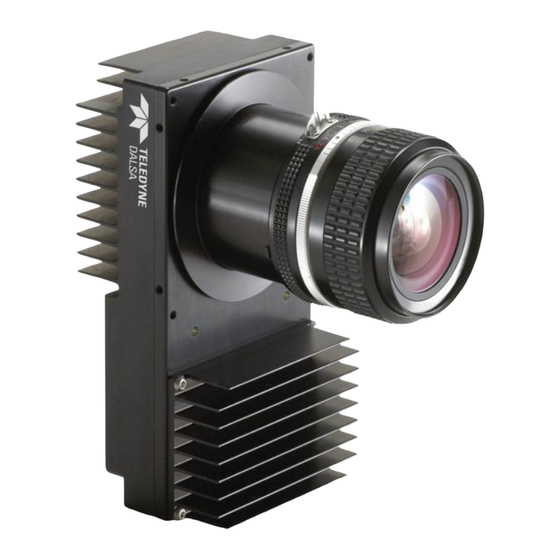
Dalsa Piranha HS Series User Manual
Hide thumbs Also See for Piranha HS Series:
Table of Contents

Advertisement

Quick Links

Piranha HS-xx
Camera User's Manual
HS-80-08k40
HS-80-08k80
HS-40-04k40
20-Aug-07
03-032-10095-14
www.dalsa.com

Advertisement

Table of Contents
loading
Need help?

Need help?

Do you have a question about the Piranha HS Series and is the answer not in the manual?

Questions and answers

Summary of Contents for Dalsa Piranha HS Series

  • Page 1 Piranha HS-xx Camera User’s Manual HS-80-08k40 HS-80-08k80 HS-40-04k40 20-Aug-07 03-032-10095-14 www.dalsa.com...
  • Page 2 Piranha HS-xx User Manual © 2007 DALSA. All information provided in this manual is believed to be accurate and reliable. No responsibility is assumed by DALSA for its use. DALSA reserves the right to make changes to this information without notice. Reproduction of this manual in whole or in part, by any means, is prohibited without prior permission having been obtained from DALSA.
  • Page 3: Table Of Contents

    3.4.5 Setting a Pretrigger ..........................50 3.5 Data Processing................................50 3.5.1 Setting a Region of Interest........................50 3.5.2 Analog and Digital Signal Processing Chain ..................51 3.5.3 End-of-line Sequence..........................66 3.6 Saving and Restoring Settings.............................68 3.6.1 Saving and Restoring Factory and User Settings...................68 DALSA 03-032-10095-14...
  • Page 4 A1 Camera Link Bit Definitions............................97 A2 Camera Link Configuration Tables ..........................97 Error Handling and Command List ___________________________________________ 103 B1 Error Handling ................................103 B2 Commands: Quick Reference ............................105 EMC Declaration of Conformity______________________________________________ 116 Revision History ________________________________________________________ 118 Index _______________________________________________________________ 121 03-032-10095-14 DALSA...
  • Page 5: Introduction To The Piranha Hs-Xx Camera

    Selectable Area or TDI Mode of operation. Area Mode facilitates camera alignment and focusing. Area mode can also be used for regular operation. • Selectable pixel size (binning) • Flat-field correction—minimizes lens vignetting, non-uniform lighting, and sensor FPN and PRNU, DALSA 03-032-10095-14...
  • Page 6 Description The Piranha HS camera family represent DALSA's latest generation of high sensitivity, TDI based cameras. The Piranha HS family maximizes system throughput and provides the largest number of pixels available in a TDI camera. All cameras are capable of bi- directionality with up to 96 stages of integration.
  • Page 7: Camera Performance Specifications

    Camera Size 85 x 85 x 55.4 lxhxw Mass <500 Connectors power connector 6 pin male Hirose data connector MDR26 female Electrical Units Interface Input Voltage Volts +12 to +15 ±5% Power Dissipation Operating °C 0 to 50 Temperature DALSA 03-032-10095-14...
  • Page 8 0 dB gain +10 dB gain Analog Broadband DN/nJ/ Responsivity @540nm -10 dB gain 0 dB gain 1170 +10 dB gain DN p-p with correction 0 dB gain w/o correction -10 dB gain 0 dB gain +10 dB gain 03-032-10095-14 DALSA...
  • Page 9 Imager Format Bidirectional TDI Resolution pixels 8192 Pixel Fill Factor Pixel Size µm Output Format (# of 4 or 8 Camera Link taps) Stage Selection 16, 32, 48, 64, 80, 96 Antiblooming 100x CCD Shift Direction seconds Change DALSA 03-032-10095-14...
  • Page 10 Units Ranges Minimum Line Rate Maximum Line Rate kHz 34.305 Throughput Mpix/sec Selectable 80, 160, or 320 Gain -10 to +10 Performance Units Minimum Typical Maximum Dynamic Range Ratio -10 dB gain 0 dB gain +10 dB gain 03-032-10095-14 DALSA...
  • Page 11 Test conditions unless otherwise noted: • TDI mode of operation. These specifications are not guaranteed for area mode of operation. • Line Rate: 10kHz • Nominal Gain setting • Light Source: Broadband Quartz Halogen, 3250k, with 700 nm IR cutoff filter installed DALSA 03-032-10095-14...
  • Page 12 (aligned to sides of camera) ±0.05 ±0.05 ±0.25 ° ±0.2 Lens Mount Hole M72x0.75 Mechanical Units Interface Camera Size 80 x 150 x 65 lxhxw Mass <800 Connectors power connector 6 pin male Hirose data connector MDR26 female 03-032-10095-14 DALSA...
  • Page 13 0 dB gain +10 dB gain Analog Broadband DN/nJ/ @540nm Responsivity -10 dB gain 0 dB gain +10 dB gain 1170 DN p-p with correction 0 dB gain w/o correction -10 dB gain 0 dB gain +10 dB gain DALSA 03-032-10095-14...
  • Page 14 All Max specifications are valid over a 0-50°C temperature range • All Typ specifications are measured at 25°C. • All values are referenced at 8-bit 1. Maximum using highest Camera Link mode and maximum line rate 2. Measured at the front plate. 03-032-10095-14 DALSA...
  • Page 15 Figure 1: PRNU Uncorrected (pk-pk) Forward or Reverse @ 10 kHz line rate and 0 dB Gain over Temperature 8K80 PRNU (pk-pk) 7.00 6.00 5.00 Average 4.00 3.00 Temperature 8K40 PRNU (pk-pk) 8.00 7.00 6.00 Average 5.00 4.00 Temperature 4K40 PRNU (pk-pk) 7.00 6.00 5.00 Average 4.00 3.00 Temperature DALSA 03-032-10095-14...
  • Page 16 Figure 2: FPN Forward or Reverse @ 10 kHz line rate and 0 dB Gain over Temperature 8K80 FPN 2.00 1.50 1.00 Average 0.50 0.00 Temperature 8K40 FPN 2.00 1.50 1.00 Average 0.50 0.00 Temperature 4K40 FPN 3.00 2.50 2.00 Average 1.50 1.00 Temperature 03-032-10095-14 DALSA...
  • Page 17 Figure 3: Random Noise Forward or Reverse @ 10 kHz line rate and 0 dB Gain over Temperature 8K80 Random Noise 1.20 0.80 Average 0.40 0.00 Temperature 8K40 Random Noise 1.20 0.80 Average 0.40 0.00 Temperature 4K40 Random Noise 1.20 0.80 Average 0.40 0.00 Temperature DALSA 03-032-10095-14...
  • Page 18 Figure 4: DC Offset Forward or Reverse @ 10 kHz line rate and 0 dB Gain over Temperature 8K80 DC Offset 7.00 6.00 5.00 Average 4.00 3.00 Temperature 8K40 DC Offset 7.00 6.00 5.00 Average 4.00 3.00 Temperature 4K40 DC Offset 7.00 6.00 5.00 Average 4.00 3.00 Temperature 03-032-10095-14 DALSA...
  • Page 19: Image Sensor

    Piranha HS-xx User Manual 1.3 Image Sensor The camera uses DALSA’s newest bidirectional TDI sensors. The camera can be configured to read out in either Forward or Reverse CCD shift direction. This is controlled by the software command Figure 5: 4 Tap Sensor Block Diagram (HS-40-04k40)
  • Page 20: Responsivity

    Piranha HS-xx User Manual 1.4 Responsivity Figure 7: Piranha HS Analog Responsivity 03-032-10095-14 DALSA...
  • Page 21: Camera Hardware Interface

    You must also set up the other components of your system, including light sources, camera mounts, host computers, optics, encoders, and so on. 2.2 Input/Output Connectors and LED The camera uses: • A diagnostic LED for monitoring the camera. See LED Status Indicator in section 2.2.1 LED Status Indicator for details. DALSA 03-032-10095-14...
  • Page 22 Camera Link (Medium or Full Configuration) +12V to +15V and Ground WARNING: It is extremely important that you apply the appropriate voltages to your camera. Incorrect voltages will damage the camera. See 2.2.2 Power Connector for more details. 03-032-10095-14 DALSA...
  • Page 23: Led Status Indicator

    • Use high-quality supplies to minimize noise. • Use an isolated type power supply to prevent LVDS common mode range violation. Note: Camera performance specifications are not guaranteed if your power supply does not meet these requirements. DALSA 03-032-10095-14...
  • Page 24: Camera Link Data Connector

    Piranha HS-xx User Manual DALSA offers a power supply with attached 6’ power cable that meets the Piranha HS camera’s requirements, but it should not be considered the only choice. Many high quality supplies are available from other vendors. Visit the www.dalsa.com...
  • Page 25 **3M part 14X26-SZLB-XXX-0LC is a complete cable assembly, including connectors. Unused pairs should be terminated in 100 ohms at both ends of the cable. Inner shield is connected to signal ground inside camera Table 9: DALSA Camera Control Configuration Signal Configuration...
  • Page 26: Camera Link Video Timing

    Piranha HS-xx User Manual See Appendix B for the complete DALSA Camera Link configuration table, and refer to the DALSA Web site, vfm.dalsa.com, for the official Camera Link documents. Input Signals, Camera Link The camera accepts control inputs through the Camera Link MDR26F connector.
  • Page 27 VTransTime HCCD Frequency HCCD Read Overhead HS 4k: 35 pixels, HS 8k: 34 pixels HTime= HCCD Read Overhead + HCCD Pixels/Tap HTime HCCD Frequency CCD Readout Time CCDReadoutTime = FrameOverhead + HTime + VTransTime x Vertical Binning Factor DALSA 03-032-10095-14...
  • Page 28 IMPORTANT: This camera uses the Internal HTime falling edge of EXSYNC User LVAL to trigger line readout, unlike previous DALSA Figure 15: Piranha HS-xx Area Mode Timing (Linestore Limited) cameras, which used the rising edge. EXSYN User FVAL Internal HTime...
  • Page 29: Software Interface: How To Control The Camera

    The serial interface uses a simple ASCII-based protocol and the PC does not require any custom software. Note: This command set has changes from previous DALSA cameras. Do not assume that the Piranha HS commands perform similarly to older cameras. Serial Protocol Defaults •...
  • Page 30 There are two different help screens available. One lists all of the available commands to configure camera operation. The other help screen lists all of the commands available for retrieving camera parameters (these are called “get” commands). 03-032-10095-14 DALSA...
  • Page 31 0-16:-10.0-+10.0 set analog offset 0-16:0-255 set binning horizontal 1/2/4/8/ set baud rate 9600/19200/57600/115200/ set binning vertical set ccd direction set digital offset 0-16:0-511 set exposure mode 3/7/ set exposure time DALSA 03-032-10095-14...
  • Page 32 1-8192:1-96:1-8192:1-96 reset pixel coeffs restore user settings set analog gain 0-16:-10.0-+10.0 set analog offset 0-16:0-255 set binning horizontal 1/2/4/8/ set baud rate 9600/19200/57600/115200/ set binning vertical set_ccd_direction set digital offset 0-16:0-511 set exposure mode 2/3/4/5/6/7/8/ 03-032-10095-14 DALSA...
  • Page 33: First Power Up Camera Settings

    • Factory calibrated FPN and PRNU coefficients using the following process: (line rate of 10000Hz) ssf 10000 (analog gain calibrated to an average pixel value of 3280) ccg 2 0 3280 (fpn calibration) (prnu calibration) ssg 0 0 DALSA 03-032-10095-14...
  • Page 34: Command Categories

    Set Digital Offset (sdo) Calculate PRNU (ccp) Calculate PRNU Algorithm (cpa) Enable Pixel Coefficients (epc) Set PRNU Coefficient (spc) Set FPN Coefficient (sfc) Set PRNU Range (spr) Set FPM Range (sfr) Set Background Subtract (ssb) Set Digital System Gain (ssg) 03-032-10095-14 DALSA...
  • Page 35: Sensor Output Format

    See section 3.6 Saving and Restoring Settings for an explanation on how user settings are stored and retrieved for each mode. • Flat field correction is not available in Area Mode Example tdi 1 DALSA 03-032-10095-14...
  • Page 36: Selecting The Number Of Ccd Integration Stages

    See the following figures for an illustration of CCD shift direction in relation to object movement. • Note that some commands that require longer processing time, like ccg, delay implementation of an external direction change. Example scd 1 03-032-10095-14 DALSA...
  • Page 37: Increasing Sensitivity With Binning

    2 and your horizontal binning to 2, your pixel size increases from 7µm x 7µm (no binning) to 14µm x 14µm (2x2 binning). Figure 18: 2x2 Binning in Area Mode DALSA 03-032-10095-14...
  • Page 38 3. Also, pixel 10 is included in the same data group as pixel 9, so pixel 10 is now part of the region of interest. To see how the region of interest start and stop values have been rounded, use the command get roi 03-032-10095-14 DALSA...
  • Page 39: Exposure Mode And Line/Frame Rate

    (CC1). When operating in TDI Mode, it is important that the line rate used matches the web speed. Failure to match the web speed will result in smearing. Refer to the DALSA application note, “Line Scan/TDI Line Scan Calculation Worksheet” located on the http://mv.dalsa.com/...
  • Page 40 Related Commands: Example: sem 3 Table 12: Piranha HS Exposure Modes Programmable Frame Rate Programmable Exposure Time Mode SYNC Description External Maximum exposure time with no charge reset. Internal Internal sync, maximum exposure time with no charge reset. 03-032-10095-14 DALSA...
  • Page 41 Note: In TDI mode the frame period equals the line period. Figure 25: Mode 7 Camera Timing Frame Period Frame Period Exposure Time Exposure Time Readout Readout Internal Sync set with Command EXSYNC Falling EXSYNC Falling Edge ignored Edge ignored during readout during readout DALSA 03-032-10095-14...
  • Page 42 The camera does not automatically change the frame rate after you change binning or stage selection values. You may have to adjust your frame rate to avoid ignored syncs. • To return the camera’s frame rate, use the commad ssf. Related Commands: Example: ssf 10000 03-032-10095-14 DALSA...
  • Page 43: Camera Output Format

    In the following tables, a CCD tap refers to the actual physical taps on the sensor, while the Camera Link taps refer to the way the data is configured for output over Camera Link. For a diagram illustrating sensor taps, see section 1.3 Image Sensor. DALSA 03-032-10095-14...
  • Page 44 CL tap 3(2049-3072) (max line rate 2 = CCD tap 2 CL tap 4(3073-4096) 36563Hz) 3 = CCD tap 3 = CL tap 1(4096-3073) smm 1 4 = CCD tap 4 CL tap 2(3072-2049) CL tap 3(2048-1025) CL tap 4(1024-1) 03-032-10095-14 DALSA...
  • Page 45 7 = CCD tap 13+14 = CL tap 1(8192-7169) 34305Hz) smm 1 8 = CCD tap 15+16 CL tap 2(7168-6145) CL tap 3(6144-5121) CL tap 4(5120-4097) CL tap 5(4096-3073) CL tap 6(3072-2049) CL tap 7(2048-1025) CL tap 8(1024-1) DALSA 03-032-10095-14...
  • Page 46 7 = CCD tap 13+14 = CL tap 1(8192-7169) (max line rate smm 1 8 = CCD tap 15+16 CL tap 2(7168-6145) 37629Hz) CL tap 3(6144-5121) CL tap 4(5120-4097) CL tap 5(4096-3073) CL tap 6(3072-2049) CL tap 7(2048-1025) CL tap 8(1024-1) 03-032-10095-14 DALSA...
  • Page 47: Setting The Camera Link Mode

    • To obtain the current Camera Link mode, use the command clm. • The bit patterns are defined by the DALSA Camera Link Roadmap available at http://mv.dalsa.com/. Related Commands Example: clm 15 DALSA...
  • Page 48: Setting The Camera Throughput

    This command is available in both TDI and Area Mode. • Refer to the following figures and tables for an explanation of pixel readout and mirror direction. • Refer to section 1.3 Image Sensor for sensor architecture diagrams that illustrate sensor readout direction. 03-032-10095-14 DALSA...
  • Page 49 3073- 4097- 5121- 6145- 7169- 2048 3072 4096 5120 6144 7168 8192 Software command smm 0 Right to Left 8192- 7168- 6144- 5120- 4096- 3072- 2048- 1024-1 7169 6145 5121 4097 3073 2049 1025 Software command smm 1 DALSA 03-032-10095-14...
  • Page 50: Setting A Pretrigger

    The start and end rows will be clipped to the stage selection if necessary. A “clipped to max” warning message is returned. Related Commands ccg, cao, cpa, gl, gla, ccf, ccp, Example: roi 10 1 50 1 (TDI Mode) 03-032-10095-14 DALSA...
  • Page 51: Analog And Digital Signal Processing Chain

    Optimizing offset performance and gain in the analog domain allows you to achieve a better signal-to-noise ratio and dynamic range than you would achieve by trying to optimize the offset in the digital domain. As a result, perform all analog adjustments prior to any digital adjustments. DALSA 03-032-10095-14...
  • Page 52 Section Analog Signal Processing provides a detailed description of all analog processing chain commands. Section Calibrating the Camera to Remove Non-Uniformity (Flat Field Correction) provides an overview of how to perform flat field calibration. Section Digital Signal Processing provides a detailed description of all digital processing chain commands. 03-032-10095-14 DALSA...
  • Page 53 A/D converter. Syntax: sag t f Syntax Elements: Tap selection. Use 0 for all taps or 1 to number of CCD taps for individual tap selection. Gain value in a range from –10 to +10dB. Example: sag 0 5.2 DALSA 03-032-10095-14...
  • Page 54 In the following example, analog gain is being set for a tap inside the region of interest. The peak value of the tap is calibrated to the specified target value and all other taps remain unchanged. 03-032-10095-14 DALSA...
  • Page 55 3040. Gain values for all other taps are left unchanged. 4095 Region of Interest 3040 Video Video 2600 8192 6400 P i x e l N u m b e r After analog gain calibration Before analog gain calibration DALSA 03-032-10095-14...
  • Page 56 Purpose: Sets the analog offset. The analog offset should be set so that it is at least 3 times the rms noise value at the current gain. DALSA configures the analog offset for the noise at the maximum specified gain and as a result you should not need to adjust the analog offset.
  • Page 57 • Lens and light source non-uniformity Correction is implemented such that for each pixel: =[(V - FPN( pixel ) - digital offset) * PRNU(pixel) – Background Subtract] x System Gain output input where digital output pixel value output DALSA 03-032-10095-14...
  • Page 58 Correction results are valid only for the current analog gain and offset values. If you change these values, it is recommended that you recalculate your coefficients. 03-032-10095-14 DALSA...
  • Page 59 5.  If you will be operating the camera in the opposite camera shift direction,      repeat steps 2 through 4 after changing direction. 6.  To verify output, enable the FPN coefficients using the command  epc 1 0 .       You should see close to zero output.  Perform PRNU correction next to determine the multiplication Perform PRNU correction factors required to bring each pixel to the required value (balance target) for  flat, white output.  1.  Place a white reference in front of the camera and remove lens cap. 2.  Verify that the output signal level is within range by issuing the command       or   . If the signal level is too low, adjust the analog gain ( ) or use the      automated  algorithm  ccg   0       DALSA recommends a target value of about 80% of maximum signal swing      per tap. If you change the gain,  FPN coefficients should be recalculated.  3.  Issue the command   or  cpa 2  i  where i is equal to or greater than the maximum      pixel in the image. The camera will respond with OK> if no error occurs. 4.   After the correction is complete, you must save these settings to non‐volatile      memory so they will be remembered and be reusable. To do so, issue the      commands  wpc    where  is the coefficient set to save and    .      Forward and reverse direction settings are stored separately and coefficients must      be saved before switching direction.
  • Page 60 Use this command in conjunction with the command (described above). • DALSA recommends that i is never set below 4096. Setting i to 0 will result in only 0 output data. • Digital offset is set to zero after sending the...
  • Page 61 ) (see Direction Control on scd 2 page 26). Direction control must be stable while the camera is calculating coefficients. • Available in TDI Mode only. • Save coefficients before changing directions, changing operating mode, or powering off. Related Commands: ccp, Example: DALSA 03-032-10095-14...
  • Page 62 The first pixel number of the range. The last pixel number of the range. Coefficient value in a range from 0-2048. Notes: • The first pixel of the range must be less than the last. Example: sfr 1 100 80 03-032-10095-14 DALSA...
  • Page 63 13% of pixels within a tap are above the value specified in the target value parameter. PRNU calibration then occurs using the peak pixel in the region of interest. This algorithm is recommended for use only when FPN is DALSA 03-032-10095-14...
  • Page 64 Perform all analog adjustments before calibrating PRNU. Notes: • This command performs the same function as the command but forces you to enter a target value. • Calibrate FPN before calibrating PRNU. If you are not performing FPN calibration then issue the (reset pixel 03-032-10095-14 DALSA...
  • Page 65 Syntax: dpc x1 x2 Syntax Elements: Start pixel to display in a range from 1 to (sensor pixel count-1). End pixel to display in a range from x1 +1 to sensor pixel count. DALSA 03-032-10095-14...
  • Page 66: End-Of-Line Sequence

    "aa" and "55", you can 5’s verify cabling (i.e. no stuck bits) A’s 4 bit counter LSB justified Counter increments by 1. Use this value to verify that every line is output (Upper 4 bits are row counter in Area Mode) 03-032-10095-14 DALSA...
  • Page 67 Sets the upper threshold limit to report in the end-of-line sequence. Syntax: sut i Syntax Elements: Upper threshold limit in range from 0 to 4095. • Notes: LVAL is not high during the end-of-line statistics. Related Commands: Example: sut 1024 DALSA 03-032-10095-14...
  • Page 68: Saving And Restoring Settings

    Forward direction and an analog gain value of +3db in Reverse direction. Forward and Reverse direction settings are saved simultaneously with the command. Note that when you switch directions, the settings saved for that direction are automatically loaded. 03-032-10095-14 DALSA...
  • Page 69: Saving And Restoring Prnu And Fpn Coefficients

    It Note: Available in TDI is important that you save pixel coefficients before switching CCD shift direction or Mode only. current coefficient values will be lost. DALSA 03-032-10095-14...
  • Page 70 2 = Coefficient set two 3 = Coefficient set three 4 = Coefficient set four Notes: • Available in TDI mode only. • Available only when operating the camera in internal direction contol ( scd 0 Example: wfc 2 03-032-10095-14 DALSA...
  • Page 71: Rebooting The Camera

    The digital offset is not reset. 3.6.3 Rebooting the Camera The command reboots the camera. The camera starts up with the last saved settings and the baud rate used before reboot. Previously saved pixel coefficients are also restored. DALSA 03-032-10095-14...
  • Page 72: Diagnostics

    4k Camera Test Pattern Operating Mode TDI Mode Forward, smm 0, svm TDI Mode Reverse, smm 0, svm 1 TDI Mode Forward, smm 1, svm TDI Mode Reverse, smm 1, svm 1 Area Mode Forward, smm 0, svm 03-032-10095-14 DALSA...
  • Page 73 TDI Mode Forward, smm 0, svm TDI Mode Forward, smm 1, svm TDI Mode Reverse, smm 1, svm 1 Area Mode Forward, smm 0, svm Area Mode Reverse, smm 0, svm 1 Area Mode Forward, smm 1, svm DALSA 03-032-10095-14...
  • Page 74: Returning Video Information

    FPN and PRNU coefficients are not included in the data. • Values returned are in 12 bit DN. • Available in TDI Mode only. Related Commands Example: gl 10 20 03-032-10095-14 DALSA...
  • Page 75: Temperature Measurement

    If the camera reaches 75°C, the camera will shutdown and the LED will flash red. If this occurs, the camera must be rebooted using the command, or can be powered down manually. You will have to correct the temperature problem or the camera will shutdown again. DALSA 03-032-10095-14...
  • Page 76: Voltage Measurement

    DSP design revision FPGA Version: xx-xx-xxxx-xx number. Serial communication UART Baud Rate: 9600 connection speed set with the sbr command. See section Setting Baud Rate for details. Current operating mode, TDI Mode: either TDI or Area set with 03-032-10095-14 DALSA...
  • Page 77 Background Subtract: 0 0 0 0 set with the ssb command. See section Digital Signal Processing for details. Region of interest size set Region of Interest: (1,1)to(8192,1) with the roi command. See section Setting a Region of Interest for DALSA 03-032-10095-14...
  • Page 78 See section 3.4.2 Setting the Camera Link Mode for details. Camera throughput value Output Throughput: set with the sot command. See section 3.4.3 Setting the Camera Throughput for details. Pretrigger set with the spt Pretrigger command. See section 3.4.5 Setting a Pretrigger. 03-032-10095-14 DALSA...
  • Page 79 Background subtract Background Subtract: settings set with the ssb command. See section Digital Signal Processing for details. Digital gain settings set System Gain: 4096 4096 4096 with the ssg command. 4096 See section Digital Signal Processing for details. DALSA 03-032-10095-14...
  • Page 80 Returns pixel values for the pixel range specified. get gl x1 x2 Returns the average of the pixel range indicated. get gla x1 x2 Returns the frequency of the Camera Link control signal get gsf indicated, either 1, 2, 3, or 4. 03-032-10095-14 DALSA...
  • Page 81 1: Pixels readout right to left (8092 or 4096 to 1) Returns the Camera Link strobe rate. get sot Returns the PRNU coefficient for the specified pixel get spc number. x=pixel number within the range 1 to sensor pixel count. DALSA 03-032-10095-14...
  • Page 82 Returns whether PRNU coefficients have been saved. get wpc 0 = No PRNU coefficients saved 1 = Pixel coefficients have been saved Returns whether user settings have been saved. get wus 0 = No user settings saved 1 = User settings have been saved 03-032-10095-14 DALSA...
  • Page 83: Optical And Mechanical Considerations

    1) CCD IMAGING CENTER IS PLACED SYMMETRICAL WITH RESPECT TO THE CENTER OF THE FOUR M3x0.5 MOUNT HOLES. 2) ROTATION OF THE CCD IMAGING AREA IS ±0.4 DEGREES. 3) LENS MOUNT POSITION WITH RESPECT TO CCD IMAGING CENTER: X-Y ±0.12MM DALSA 03-032-10095-14...
  • Page 84: Lens Mounts

    Factors include the nature, speed, and spectral characteristics of objects being imaged, exposure times, light source characteristics, environmental and acquisition system specifics, and more. DALSA’s Web site, http://vfm.dalsa.com/, provides an introduction to this potentially complicated issue. See “Radiometry and Photo Responsivity”...
  • Page 85 The back focal length (BFL) is the distance from the image side of the lens surface to the second focal point. The object distance (OD) is the distance from the first principal point to the object. Figure 38: Primary Points in a Lens System DALSA 03-032-10095-14...
  • Page 86 Piranha HS-xx User Manual 03-032-10095-14 DALSA...
  • Page 87: Ccd Handling Instructions

    Dust can normally be removed by blowing the window surface using a compressed air blower, unless the dust particles are being held by an electrostatic charge, in which case either an ionized air blower or wet cleaning is necessary. DALSA 03-032-10095-14...
  • Page 88: Cleaning The Sensor Window

    5. Wipe the window carefully and slowly. 6. When cleaning long linear sensors, it may be easier to wipe along the width (i.e. as opposed to the length) of the sensor. 03-032-10095-14 DALSA...
  • Page 89: Troubleshooting

    The first step in troubleshooting is to verify that your camera has all the correct connections. Power Supply Voltages Check for the presence of all voltages at the camera power connector. Verify that all grounds are connected. Issue the command, , to confirm correct voltages. DALSA 03-032-10095-14...
  • Page 90: Troubleshooting Using The Serial Interface

    The test pattern is a ramp from 0 to 255DN, then starts svm 1 at 0 again. Use the test pattern to verify the proper timing and connections between the camera and the frame grabber. 03-032-10095-14 DALSA...
  • Page 91 "pixels below threshold". To activate the end-of-line sequence, use the command els 1 To disable the end-of-line sequence, use the command els 0 Use the commands to set threshold values between 0 and 255 for 8 bit data modes, or 0 to 4096 for 12 bit data modes. DALSA 03-032-10095-14...
  • Page 92: Specific Solutions

    8. Blow off any adhering fibers or particles using dry, filtered compressed air. Stuck Bits If data bits seem to be stuck or do not change, check that the camera is not saturated by preventing light from entering. To verify the data path integrity, check the levels of the 2 03-032-10095-14 DALSA...
  • Page 93 If you have verified that your exposure time is consistent and patterns of low frequency intensity variations still occur, ensure that you are using a DC or high frequency light source. DALSA 03-032-10095-14...
  • Page 94: Product Support

    Results when you run the gcp the command command please attach description with as much detail as appropriate Detailed description of problem encountered. In addition to your local DALSA representative, you may need to call DALSA Technical Sales Support: North America Europe Asia Voice:...
  • Page 95: Camera Link™ Reference, Timing, And Configuration Table

    The DALSA Camera Link Implementation Road Map (available from the http://mv.dalsa.com/ site) details how DALSA standardizes its use of the Camera Link interface. LVDS Technical Description Low Voltage Differential Signaling (LVDS) is a high speed, low power, general purpose interface standard.
  • Page 96 • Camera Control 1 (CC1) • Camera Control 2 (CC2) • Camera Control 3 (CC3) • Camera Control 4 (CC4) The HS-xx uses the following camera control signals: Table 22: DALSA Camera Control Configuration EXSYNC, negative edge active Not Used Forward Not Used...
  • Page 97: A1 Camera Link Bit Definitions

    Bit 7 Bit 7 A2 Camera Link Configuration Tables The following table provides tap reconstruction information. DALSA is working with the machine vision industry to use this table as the basis for auto configuration. Visit the http://mv.dalsa.com/ Web site and view the DALSA Camera Link Implementation Road Map document, 03-32-00450, for further details.
  • Page 98 C1/2, T6 (5121, 6144, 1, 1, 1, 1) C1/2, T7 (6145, 7168, 1, 1, 1, 1) C1/2, T8 (7169, 8192, 1, 1, 1, 1) C3/4, T1 (1, 2048, 1, 1, 1, 1) C3/4, T2 (2049,4096 1, 1, 1, 1) 03-032-10095-14 DALSA...
  • Page 99 C1/2, T8 (1024, 1, -1, 96, 1, -1) C3/4, T1 (8192, 6144, 1, 1, 96, 1) C3/4, T2 (6144, 4097, 1, 1, 96, 1) C3/4, T3 (4096, 2049, 1, 1, 96, 1) C3/4, T4 (2048, 1, 1, 1, 96, 1) DALSA 03-032-10095-14...
  • Page 100 Imager Columns<number of active columns, X> 4096 Imager Rows<number of active rows, Y> Line 1 | 96 Scan/TDI are defined as 1 Number of CCD Taps <1,2,3…..> Sensor Tap Clock Rate <xx MHz> Camera Standard <NTSC, PAL, VS, VW, MW> 03-032-10095-14 DALSA...
  • Page 101 C7/8, T1 (1, 1024, 1, 1, 96, 1) C7/8, T2 (1025, 2048, 1, 1, 96, 1) C7/8, T3 (2049, 3072, 1, 1, 96, 1) C7/8, T4 (3073, 4096, 1, 1, 96, 1) Area Mode Right to Left Readout (smm 1) DALSA 03-032-10095-14...
  • Page 102 9600, 19200, 57600, 115200 CC1 <Exsync> EXSYNC CC2 <Spare> PRIN (Area Mode only) CC3 <Forward, Spare> Forward/ReverseB CC4 <Spare> Spare DVAL out <Strobe Valid, Alternate> Strobe Valid Spare out <Spare> Spare TDI Stages TDI Mode: 16|32|48|64|80|96 Area Mode: 16|32|48|64|80|96 03-032-10095-14 DALSA...
  • Page 103: Error Handling And Command List

    Warning 09: Internal line rate Changing this parameter (e.g. vertical binning) has inconsistent with read out time> changed read out time and that is greater than the internal SYNC DALSA 03-032-10095-14...
  • Page 104 Comment Error 01: Internal error xx> Where xx is a code list below. Only output during power up. Customer should contact DALSA customer support. Error 02: Unrecognized command> Command is not valid. Error 03: Incorrect number of Too many or too few parameters.
  • Page 105: B2 Commands: Quick Reference

    Refer to Analog Signal Processing: Setting Analog Gain and Offset for details. correction calibrate fpn Performs FPN calibration and eliminates FPN noise by subtracting away individual pixel dark current. Refer to Digital Signal Processing and Processing Chain Overview and Description for details. DALSA 03-032-10095-14...
  • Page 106 Performs PRNU calibration and eliminates the difference in responsivity between the most and least sensitive pixel creating a uniform response to light. Refer to Digital Signal Processing and Processing Chain Overview and Description for details. 03-032-10095-14 DALSA...
  • Page 107 3: Base configuration, 2 taps, 12 bit output 15: Medium configuration, 4 taps, 8 bit output 16: Medium configuration, 4 taps, 12 bit output 21: Full configuration, 8 taps, 8 bit output Refer to section 3.4.2 Setting the Camera Link Mode for details. DALSA 03-032-10095-14...
  • Page 108 4055DN. correction set sample Set number of line samples averaged for pixel coefficient calculations or for output of command. Values: 256, 512, 1024. Factory setting: 1024 Refer to Returning Averaged Lines of Video on page 75 for details. 03-032-10095-14 DALSA...
  • Page 109 = Pixel start number x = Pixel end number in a range from 1 to sensor pixel count. Refer to Returning a Single Line of Video on page 74 for details. DALSA 03-032-10095-14...
  • Page 110 Reset the pixel coefficients to 0. Refer to section Enabling and Disabling Pixel Coefficients on page 66 for details. restore user settings Restore the camera's last saved user settings and FPN and PRNU coefficients. Refer to section 3.6 Saving and Restoring Settings for details. 03-032-10095-14 DALSA...
  • Page 111 FPN correction. t = Tap value. 0 for all taps or 1- number of CCD taps for individual tap selection. i = Offset in a range from 0 to 511DN. Refer to Setting Digital Offset on page61 for details. DALSA 03-032-10095-14...
  • Page 112 320 = 4 taps at 80MHz or 8 taps at 40MHz 640 = 8 taps at 80MHz Refer to section 3.4.3 Setting the Camera Throughput for details on using this command. Available settings are dependent on your camera model. 03-032-10095-14 DALSA...
  • Page 113 Refer to Setting Digital Gain on page 60 for details. stage select Sets the number of TDI stages. Allowable values are: 16,32, 48, 64,80,96 (default) Refer to 3.3.2 Selecting the Number of CCD Integration Stages for details. DALSA 03-032-10095-14...
  • Page 114 Description set upgrade feature Allows you to upgrade from an HS-80- 08k40 to an HS-80-08k80. Contact DALSA Sales for an upgrade string. set upper threshold The pixels equal to or greater than the upper threshold are checked for and reported in the end-of-line sequence in a range from 0-4095.
  • Page 115 Piranha HS-xx User Manual Mnemonic Syntax Parameters Description write user settings Write all of the user settings to EEROM. Refer to section 3.6.1 Saving and Restoring Factory and User Settings for details. DALSA 03-032-10095-14...
  • Page 116: Emc Declaration Of Conformity

    73/23/EEC and the EMC Directive 89/336/EEC and carries the CE mark accordingly. Place of Issue Waterloo, ON, CANADA Date of Issue April 2005 Name and Signature Hank Helmond Quality Manager, DALSA Corp. of authorized person This Declaration corresponds to EN 45 014. 03-032-10095-14 DALSA...
  • Page 117 Piranha HS-xx User Manual DALSA 03-032-10095-14...
  • Page 118: Revision History

    Added spt (set pretrigger) command to section 3.6.5 Setting a Pretrigger and B2 Commands: Quick Reference. Updated the 4k mechanical drawing in Figure 34: Piranha HS-xx Mechanical Dimensions. Updated back focal distance (M42 for 4k and M72 for 8k) spec from 6.78 to 6.56. 03-032-10095-14 DALSA...
  • Page 119 New specifications over temperature graphs added to section 1.2. Maximum line rate updated in Tables 13, 14, and 15 on pages 40 to 42. Other minor wording or cosmetic changes. Added note to section 3.7.1 that “The following diagrams show 12-bit pixel DALSA 03-032-10095-14...
  • Page 120 31, 63, and 108. Two new commands added: Set FPN Range (sfr), and Set PRNU Range (spr), pages 34, 62, and 65. Revised fill factor percentage for the HS-80-8k80 performance specifications from 100% to 90%. Page 12, table 4. 03-032-10095-14 DALSA...
  • Page 121: Index

    66 framegrabber parameters, 98 enabling, 66 FVAL, 26, 95 loading, 66 resetting, 66 command format, 30 gain, 5, 8, 10, 11, 13, 51, 54, 56 parameters, 30 analog, 57 commands, 34 gain ranges, 8, 10, 13 list, 105 DALSA 03-032-10095-14...
  • Page 122 74 STROBE, 26 stuck bits, 92 NEE, 8, 11, 13 noisy output, 92 readout direction, 48 reconstruction, 97 offset TDI Mode, 35 optimizing, 51 Technical Sales Support, 94 online help, 30 temperature operating measurement, 75 modes, 39 03-032-10095-14 DALSA...
  • Page 123 Piranha HS-xx User Manual test patterns, 72 test patterns, 90 timing, 27, 28 video data, 75, 95 camera, 27, 28 voltage Camera Link, 27, 28 measurement, 76 mode 3, 41 mode 7, 41 trigger external, 26 warning messages, 103 troubleshooting, 89 DALSA 03-032-10095-14...

This manual is also suitable for:

Hs-80-08k40Hs-80-08k80Hs-40-04k40

Table of Contents