
Subscribe to Our Youtube Channel
Related Manuals for Dalsa P4-CC-08K050-00-R


Summary of Contents for Dalsa P4-CC-08K050-00-R
- Page 1 Piranha4 Color P4-CC-08K050-00-R Camera User’s Manual 03 August 2012 03-032-20156-00 www.teledynedalsa.com...
- Page 2 Piranha4 8K Camera Color User's Manual © 2012 Teledyne DALSA, Inc. All information provided in this manual is believed to be accurate and reliable. No responsibility is assumed by Teledyne DALSA for its use. Teledyne DALSA reserves the right to make changes to this information without notice.
-
Page 3: Table Of Contents
Power on the camera ............................26 Connect to the frame grabber ......................... 26 Connect to the camera ............................ 26 Check LED Status ............................27 Software Interface ............................27 Using Sapera CamExpert with Piranha4 Cameras ......................28 CamExpert Panes ............................29 Teledyne DALSA 03-032-20156-00... - Page 4 Appendix C: Quick Setup and Image Acquisition ___________________________________________________________ 72 Appendix D: The Sensor Window _____________________________________________________________________ 75 Cleaning and Protecting Against Dust, Oil, and Scratches ................75 Cleaning the Sensor Window .......................... 76 EMC Declaration _________________________________________________________________________________ 77 Revision History _________________________________________________________________________________ 78 Index ________________________________________________________________________________________ 79 03-032-20156-00 Teledyne DALSA...
-
Page 5: System Precautions
The charge normally dissipates within 24 hours and the sensor returns to normal operation. Additional information on cleaning the sensor window and protecting it against dust, oil, blemishes, and scratches can be found here, Appendix D: Sensor Window: Cleaning and Protecting Against Dust, Oil, Scratches. Teledyne DALSA 03-032-20156-00... -
Page 6: The Piranha4 Color Camera
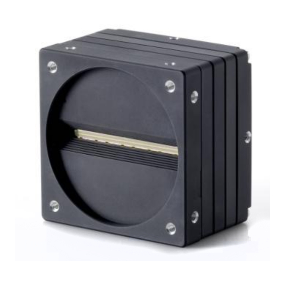
1. The Piranha4 Color Camera Camera Highlights Based on Teledyne DALSA's unique CMOS color line scan sensor architecture, the new Piranha4 8k bilinear color camera provides outstanding signal-to-noise for high speed imaging. The P4-8k has 8k resolution with a 7 µm x 7 µm pixel size for optimized optical design. The camera delivers a max line rate of 50 kHz in a high responsivity summing mode. -
Page 7: Camera Performance Specifications
Piranha4 8K Color Camera User's Manual Models The camera is available in the following configurations: Table 1: Camera Models Overview Model Number Description P4-CC-08K050-00-R 8k resolution, 50 kHz line rate, Camera Link interface. Table 2: Software Software Product Number / Version Number Camera firmware Embedded within camera GenICam™... -
Page 8: Certifications
Piranha4 cameras are GenICam compliant. They implement a superset of the GenICam™ Standard Features Naming Convention specification V1.5. This description takes the form of an XML device description file respecting the syntax defined by the GenApi module of the GenICam™ specification. The 03-032-20156-00 Teledyne DALSA... -
Page 9: Responsivity
(dual line summing). Figure 1: Spectral Responsivity vs. Wavelength FPN Characteristics with Temperature Figure 2: FPN Derating Chart Teledyne DALSA 03-032-20156-00... -
Page 10: Sensor Shift Direction Example
Image Sensor The Piranha4 bilinear color camera is based on Teledyne DALSA’s bilinear CMOS sensor and designed such that the first line of this two line sensor has red (R) and blue (B) alternating pixels, while the second line has all green (G) pixels. -
Page 11: Mechanicals
Piranha4 8K Color Camera User's Manual Mechanicals [ADD MECHANICAL FROM PDF] Figure 5: Camera Mechanical Teledyne DALSA 03-032-20156-00... -
Page 12: Camera Mounting And Heat Sink Considerations
BE DUPLICATED, OR ITS CONTENT USED OR DISCLOSED (IN WHOL Teledyne DALSA recognises that each customer’s application can be unique. In consideration, the P4 camera heat sinks have been designed in such a way that they can be repositioned on the different faces of the camera or removed entirely, depending on the mounting configuration and its heat sinking potential. -
Page 13: Quick, Simple Steps To Acquire An Image
Piranha4 camera, an overview of the steps required to get this camera operational and acquiring images quickly can be found in Appendix C: Basic Setup and Image Acquisition. Teledyne DALSA 03-032-20156-00... -
Page 14: Software And Hardware Setup
ASCII-based commands. A complete list of the commands can be found in the appendix: ASCII User Command Reference. 4. Operate the Camera At this point you will be ready to start operating the camera in order to acquire images, set camera functions, and save settings. 03-032-20156-00 Teledyne DALSA... -
Page 15: Step 1. Install And Configure The Frame Grabber, And Software (Including Gui)
These cameras implement the Camera link specification, which defines the device capabilities. The Camera link XML device description file is embedded within the camera firmware allowing Camera link-compliant applications to recognize the cameras‘ capabilities immediately after connection. Teledyne DALSA 03-032-20156-00... -
Page 16: Step 2. Connect Data, Trigger, And Power Cables
The figure below shows the MDR26 Camera Link Connector and the tables that follow list the Camera Link Base, Medium, and Deca configurations. For detailed information on Camera Link please refer to the Camera Link Road Map available from the Knowledge Center on the Teledyne DALSA Web site. 03-032-20156-00 Teledyne DALSA... - Page 17 Note *Exterior Overshield is connected to the shells of the connectors on both ends. Unused pairs should be terminated in 100 ohms at both ends of the cable. Inner shield is connected to signal ground inside camera Teledyne DALSA 03-032-20156-00...
-
Page 18: Camera Link Bit Definitions
Spare Direction Spare Table 4: Camera Control Configuration For additional Camera Link documentation refer to the Teledyne DALSA Web site‘s Knowledge Center application notes. RGB 8 bit CL Base, max line rate 10 kHz without AOI and 85 MHz CL Clock This timing can be used for applications that require line rates only up to 10 kHz and therefore can use Camera Link Base mode with only one cable. - Page 19 Line rates up to 70 kHz can be achieved by using the Area of Interest (AOI) feature; where the smaller the AOI, the greater the potential line rate. Teledyne DALSA 03-032-20156-00...
-
Page 20: Rgb 8 Bit Cl Deca, Max Line Rate 34 Khz Without Aoi And 85Mhz Cl Clock
Values for blue odd numbered pixels are interpolated from the neighbouring blue even numbered pixels. Line rates up to 70 kHz can be achieved by using the Area of Interest (AOI) feature; where the smaller the AOI, the greater the potential line rate. 03-032-20156-00 Teledyne DALSA... - Page 21 Area of Interest (AOI) feature, where the smaller the AOI results in increased potential line rates. Note: when using an AOI with this RGBG mode, you must consider the available (i.e. potential lack of) red and blue pixel data at the AOI boundaries when they are performing interpolation. Teledyne DALSA 03-032-20156-00...
- Page 22 Note: when using an AOI with this RGBG mode, the user must consider the available red and blue pixel data at the AOI boundaries when they are performing interpolation When using the AOI feature, there are specific AOI rules with respect to AOI sizes and boundaries that must be adhered to, see below. 03-032-20156-00 Teledyne DALSA...
-
Page 23: Custom Aoi Rules
1023 (i.e. 8, 960, 7680 are allowed, 12 is not allowed). 3) In mirror mode, the first pixel of each AOI (AOI right edge) must have the location 8i + 7, where i = 0,1,2 .., 1023 (i.e. 7, 15, 4095 are allowed, 8 is not allowed). Teledyne DALSA 03-032-20156-00... -
Page 24: Camera Link Cable Quality And Length
Depending upon the mode of operation the high time of the EXSYNC signal can represent the integration period. Note: The EXSYNC signal is measured at CC1 and will give a ―true‖ measurement (i.e. within the measurement resolution of 25 ns) even though the camera will only trigger at a maximum of 50 KHz. 03-032-20156-00 Teledyne DALSA... -
Page 25: Output Signals, Camera Link Clocking Signals
Keep leads as short as possible in order to reduce voltage drop. Use high-quality supplies in order to minimize noise. Note: If your power supply does not meet these requirements, then the camera performance specifications are not guaranteed. Teledyne DALSA 03-032-20156-00... -
Page 26: Leds
1. Start a new Sapera CamExpert application (or equivalent Camera Link compliant interface) by double clicking the desktop icon created during the software installation. 2. In the Devices list area on the left side, select the COM port below the Camera Link label. 03-032-20156-00 Teledyne DALSA... -
Page 27: Check Led Status
Sensor Control menu in the camera window you can control the line rate and exposure times. Note: the camera uses two CamExpert windows to send commands and display the results. One window controls the camera and the other is used for image acquisition and display. Teledyne DALSA 03-032-20156-00... -
Page 28: Using Sapera Camexpert With Piranha4 Cameras
CamExpert. The central section of CamExpert provides access to the camera features and parameters. Note: The availability of the features is dependent on the CamExpert user setting. 03-032-20156-00 Teledyne DALSA... -
Page 29: Camexpert Panes
Piranha4 8K Color Camera User's Manual CamExpert Panes Figure 12. CamExpert’s Camera Control Window Teledyne DALSA 03-032-20156-00... - Page 30 Display pane: Provides a live or single frame acquisition display. Frame buffer parameters are shown in an information bar above the image window. Control Buttons: The Display pane includes CamExpert control buttons. These are: Acquisition control button: Click once to start live grab, click again to stop. 03-032-20156-00 Teledyne DALSA...
-
Page 31: Review A Test Image
{102, 103, 104…} Blue Value: {204, 205, 206…} Values roll over at 255. 3. Grey Ramp At this point you are ready to start operating the camera in order to acquire images, set camera functions, and save settings. Teledyne DALSA 03-032-20156-00... -
Page 32: Camera Operation
CamExpert GUI shown in the following examples. Parameters such as camera model, firmware version, sensor characteristics, etc. are read to uniquely identify the connected device. The camera information parameters are grouped together as members of the Camera Information set. Figure 14. CamExpert’s Camera Information Window 03-032-20156-00 Teledyne DALSA... -
Page 33: Verify Temperature And Voltage
The current settings can be saved (thereby becoming the user setting) using the User Set Save parameter. A previously saved user setting (User Set 1 to 8) or the factory settings can be restored using the User Set Selector and User Set Load parameters. Teledyne DALSA 03-032-20156-00... - Page 34 The command User Set Save saves the current settings to non-volatile memory as a User Set. The camera automatically restores the last saved user settings when it powers up. To restore the last saved user settings, select the User Set parameter you want to restore and then select the User Set Load parameter. 03-032-20156-00 Teledyne DALSA...
-
Page 35: Camera Link Configuration
The camera can grab images in one of three ways. You determine the three imaging modes using a combination of the Exposure Mode parameters (including I/O parameters), Exposure Time and Line Rate parameters. Teledyne DALSA 03-032-20156-00... -
Page 36: Exposure Modes In Detail
2. External Line Rate and External Exposure Time (Trigger Width) In this mode, EXSYNC sets both the line period and the exposure time. The rising edge of EXSYNC marks the beginning of the exposure and the falling edge initiates readout. Note: 03-032-20156-00 Teledyne DALSA... - Page 37 In this mode, the line rate is set externally with the falling edge of EXSYNC generating the rising edge of a programmable exposure time. GenICam parameters to set: I / O Controls > Trigger Mode > On Sensor Control > Exposure Mode > Timed Teledyne DALSA 03-032-20156-00...
- Page 38 Falling edge triggers end of exposure / start of readout Exposure Time Readout Line Time Notes: 1. Exposure time > 11 micro-seconds 2. Readout time = 14 micro-seconds 3. One addition falling edge during exposure is latched Figure 17. Exposure Modes 03-032-20156-00 Teledyne DALSA...
-
Page 39: Set Line Rate
This feature is only available when the Exposure Mode parameter is set to Timed. The allowable exposure range is from 11 µs to 3,000 µs, dependent on the value of the internal line rate. GenICam parameters: Sensor Controls > Exposure Time (Timed Exposure Mode) > 11 µs to 3,000 µs. Teledyne DALSA 03-032-20156-00... -
Page 40: Control Gain And Black Level
The baud rate sets the speed (in bits per second—bps) of the serial communication port and is available as part of the Serial Port Control parameters. Serial Port Control Action Parameter Options Control the baud rate used by the Baud Rate 9600 (factory default) camera‘s serial port 19200 57600 115200 230400* 460800* 921600* 03-032-20156-00 Teledyne DALSA... -
Page 41: Pixel Format
When in TDI stages 2, this command lets you select the Internal or external direction control. Use this feature to accommodate object direction change on a web and to mount the camera "upside down." Scan Direction Read the current direction. Teledyne DALSA 03-032-20156-00... -
Page 42: Pixel Readout Direction (Mirroring Mode)
The feature Camera Reset, part of the Transport Layer set, resets the camera. The camera resets with the default settings, including a baud rate of 9600. Camera Information Parameter Description Camera Reset Resets the camera and puts in the default settings, including a 9600 baud rate. 03-032-20156-00 Teledyne DALSA... -
Page 43: Calibrating The Camera
3. The white balancing gains are used set the red, green and blue response to equal values with a white target in the field of view. The white balance gains can be individually set by the user, but will be overridden by the camera when the camera performs PRNU calibration or white balancing commands. Teledyne DALSA 03-032-20156-00... - Page 44 MacBeth Chart© illuminated by the application‘s light source and processing the image using a color correction demonstration tool provided as part of Teledyne DALSA‘s Sapera Processing software. This tool will generate the desired color correction file that can be downloaded to the camera.
- Page 45 3. Range 0 to 31 DN, 8 bit 4. Default value is 0 DN for each pixel flatfieldCalibrationPRNU 1. Use ―flatfieldCorrectionAlgorithm‖ to calculate the per pixel gain to achieve the specified target output. Teledyne DALSA 03-032-20156-00...
- Page 46 1. Single value added to each pixel 2. Range -32 to +31 DN 3. Positive values may be used to measure dark noise Gain 1. Floating point digital multiplier applied to each pixel 2. Range 1x to 10x 03-032-20156-00 Teledyne DALSA...
-
Page 47: Appendix A: Genicam Commands
String Values ―P4_CC_08K050_00_R‖ Name DeviceVendorName Display Name "Vendor‖ Name Space Standard Visibility Beginner Access Read-only Type String Values ―Teledyne DALSA‖ Name DeviceID Display Name "Serial Number‖ Name Space Standard Visibility Expert Access Read-only Type String Values e.g. ―15005465‖ Teledyne DALSA... - Page 48 If the LED is green then this feature will return the string ―Good‖ If the LED is red then it will be a string of flags that indicate all the things that are wrong More than one flag can be set 03-032-20156-00 Teledyne DALSA...
- Page 49 "Power-on User Set‖ Name Space Standard Visibility Beginner Access Read-Write Type Enumeration Values "Factory" "UserSet1" to ―UserSet8‖ Description This value specifies which user set will be loaded at power-on. This value is automatically saved when written. Teledyne DALSA 03-032-20156-00...
- Page 50 This feature is not available when UserSetSelector equals "Factory" Name SecurityUpgrade Display Name "License Key‖ Name Space Custom Visibility Guru Access Read-Write Type String Description A license key string will be sent by Teledyne DALSA if a feature upgrade is purchased. 03-032-20156-00 Teledyne DALSA...
-
Page 51: Devicesensorcontrol "Camera Control" Group
Name Space Standard Visibility Beginner Access Read- Write Type Enumeration Values ―Timed‖ - Exposure time is set with ExposureTime ―TriggerWidth‖ - Exposure time equals high time of CC1 signal. Description ―TriggerWidth‖ is only available when TriggerMode equals ―On‖ Teledyne DALSA 03-032-20156-00... - Page 52 CC3 low selects forward, high selects reverse Name SensorScanDirection Display Name "Internal Direction‖ Name Space Standard Visibility Beginner Access Read-Write Type Enumeration Values "Forward" "Reverse" Description This feature is used with automatically loading new settings on change of direction 03-032-20156-00 Teledyne DALSA...
- Page 53 Name Space Standard Visibility Beginner Access Read-Write Type Float Units Multiplier Values 1 to 10 Name ColorTransformationMatrixSelector Display Name " Color Transformation Matrix Selector‖ Name Space Standard Visibility Expert Access Read-Write Type Enumeration Values ―WhiteLEDFactorySet‖ ―NoCorrectionFactorySet‖ ―MatrixUserSet1‖ ―MatrixUserSet1‖ Teledyne DALSA 03-032-20156-00...
- Page 54 Name Space Standard Visibility Expert Access Read-Write Type Float Units Multiplier Values -32 < value < 32 Name ClConfiguration Display Name "Camera Link Configuration‖ Name Space Standard Visibility Beginner Access Read-Write Type Enumeration Values ―Base‖ ―Medium‖ ―Full‖ ―Deca‖ 03-032-20156-00 Teledyne DALSA...
-
Page 55: Imageformatcontrol "Image Format" Group
"Line Mirroring‖ Name Space Standard Visibility Beginner Access Read-Write Type Enumeration Values ―Off‖ ―On‖ - Pixel order is reversed Name PixelFormat Display Name "Pixel Format‖ Name Space Standard Visibility Beginner Access Read-Write Type Enumeration Values ―RGB8‖ ―G8‖ ―RGBG8 Teledyne DALSA 03-032-20156-00... - Page 56 - Range limited by existing AOI‘s and MultipleAOIWidth Name MultipleAOIWidth Display Name " AOI Width‖ Name Space Custom Visibility Expert Access Read-Write Type Integer Values 1 to 8192 - Pixel width of AOI - Range limited by existing AOI‘s and MultipleAOIOffsetX 03-032-20156-00 Teledyne DALSA...
-
Page 57: Fileaccesscontrol "File Access Control" Group
- Used for firmware upgrades ―ColorCorrectionMatrix‖ ―CameraData‖ - Download and send for customer support serialPortControl ”Serial Port” Group Name DeviceSerialPortBaudRate Display Name ―Baud Rate‖ Name Space Standard Visibility Expert Access Read-Write Type Enumeration Values ―Baud_9600‖ ―Baud_19200‖ ―Baud_57600‖ ―Baud_115200‖ ―Baud_230400‖ ―Baud_460800‖ ―Baud_921600‖ Teledyne DALSA 03-032-20156-00... -
Page 58: Dataprocessing "Flat Field" Group
Because of the low pass filter this algorithm is not able to correct pixel-to-pixel variations and so it is preferable to use the ―Basic‖ algorithm. 03-032-20156-00 Teledyne DALSA... - Page 59 Visibility Expert Access Read-Write Type Integer Values 1 to 8192 Description Together with flatfieldCalibrationROIOffsetX specifies the pixels that will be calibrated – pixel coefficients outside this region are not changed Range is limited by flatfieldCalibrationROIOffsetX Teledyne DALSA 03-032-20156-00...
- Page 60 Range 0 to 15.9998 times Name BalanceWhiteAuto Display Name "Balance White Auto‖ Name Space Custom Visibility Expert Access Read-Write Type Command Values Description Adjust color gains so that the average of each color is the same as the brightest color 03-032-20156-00 Teledyne DALSA...
-
Page 61: Transportlayercontrol "Transport Layer" Group
If a feature read or write fails then Sapera only returns that it fails – read this feature to get the actual reason for the failure Returns the last error Reading this feature clears it Teledyne DALSA 03-032-20156-00... -
Page 62: Appendix B: Ascii Commands
Piranha4 8K Camera Color User's Manual Appendix B: ASCII Commands The following commands can be used to control the Teledyne DALSA Piranha4 P4-CC-08K050-00-R camera. To access the TLC an ASCII-based communications tool, such as Hyperterminal or equivalent, must be used. -
Page 63: Commands
In Full mode pixel format G8 is possible Mnemonic Argument(s) Device 0. Factory 1. User # of lines to average 0 or 1, when factory selected above then 0. White LED 1. No correction (unity matrix) Description Color matrix selector Teledyne DALSA 03-032-20156-00... - Page 64 10. k offset 11. k offset Floating Point Value Gains: -32 to 32 Offsets: 0 to 255 Description Color Transformation Matrix Notes Value must be immediately preceded with a ―F‖ (e.g. ctv 0 f1.5) 03-032-20156-00 Teledyne DALSA...
- Page 65 2. Reset user FPN coefficients to zero and user PRNU coefficients to one 3. Scan direction controlled user set loading Description Set flat field mode Notes Mnemonic Argument(s) User Set Number 1 to 8 Description Set scan direction controlled reverse set Notes Teledyne DALSA 03-032-20156-00...
- Page 66 Color Matrix Selector: Factory 2 Color Correction Matrix: 1.000000, 0.000000, 0.000000, 0 0.000000, 1.000000, 0.000000, 0 0.000000, 0.000000, 1.000000, 0 Offset Mirror AOI Mode: CL Speed 85MHz CL Config Medium Pixel Fmt 8 bits/RGB8 CPA ROI 1-8192 USER> 03-032-20156-00 Teledyne DALSA...
- Page 67 - External Trigger <0:Off 1:On> - Test Pattern <0-2> - Default User Set <0-8> - Load User Set <0-8> - Save User Set <1-8> - Temperature - Input Voltage USER> Mnemonic Argument(s) Description Reset camera Notes Teledyne DALSA 03-032-20156-00...
- Page 68 Must not overlap with an already existing AOI Mnemonic Argument(s) Mode 0. ―Off‖ 1. ―Active‖ Description Set AOI mode Notes Mnemonic Argument(s) Baud rate 9600 57600 115200 Description Set baud rate Notes Send command and then change speed of HyperTerminal 03-032-20156-00 Teledyne DALSA...
- Page 69 Set mirroring mode Notes Mnemonic Argument(s) Selector 0. RGB8 1. G8 2. RGBG8 Description Set pixel format Notes Mnemonic Argument(s) Offset 8 bit -32 to 31 Description Set offset Notes Range changes depending on pixel format (SPF) Teledyne DALSA 03-032-20156-00...
- Page 70 1-8. User sets Description Select user set to load when camera is reset Notes The settings include all those listed by the GCP command plus the user FPN coefficients, user PRNU coefficients, and color correction matrix 03-032-20156-00 Teledyne DALSA...
- Page 71 Saves all the current settings listed by the GCP command plus the user FPN coefficients, user PRNU coefficients, and color correction matrix Mnemonic Argument(s) Description Display internal temperature in degrees Celsius Notes Mnemonic Argument(s) Description Display supply voltage Notes Teledyne DALSA 03-032-20156-00...
-
Page 72: Appendix C: Quick Setup And Image Acquisition
CamExpert provides an easy-to-use GUI that can be used to set up and evaluate the camera. The camera also comes with Teledyne DALSA‘s three letter command (TLC) interface option, which can be accessed using a suitable terminal program such as HyperTerminal™. - Page 73 The image may be darker at the edges due to lens vignetting, but this will be improved once the camera is calibrated. Calibration is performed using a white reference where your object is normally located. Use a white material that has no texture, such as a non glossy plastic. Teledyne DALSA 03-032-20156-00...
- Page 74 A software tool to generate this is available with the Sapera processing applications, which can be downloaded from the Teledyne DALSA web site (60 day free trial). You will require a MacBeth© chart with 4 x 6 color elements that you can scan past the camera to complete the generation of the matrix.
-
Page 75: Appendix D: The Sensor Window
(dark spot) and overcorrecting where the shadow used to be (white spot). While the dark spot can be potentially cleaned, the white spot is an FFC artifact that can only be corrected by another FFC calibration. Teledyne DALSA 03-032-20156-00... -
Page 76: Cleaning The Sensor Window
This procedure requires you to use multiple swabs. Discard the swab after both sides of the swab have been used once. Repeat until there is no visible contamination present. 03-032-20156-00 Teledyne DALSA... -
Page 77: Emc Declaration
EN 55011, FCC Part 15, CISPR 11, and ICES-003 Radiated emissions requirements. EN 61326-1 and EN55024 Immunity to disturbances. Changes or modifications not expressly approved by Teledyne DALSA could void the user's authority to operate the equipment. Name and Signature of authorized person Hank Helmond Quality Manager, Teledyne DALSA Corp. -
Page 78: Revision History
Piranha4 8K Camera Color User's Manual Revision History Revision Number Change Description Revision Date Initial release. 03 August 2012 03-032-20156-00 Teledyne DALSA... -
Page 79: Index
41 performance specifications, 7 pixel format, 41 power EMC Declaration of connector, 25 Conformity, 77 connectors, 25 exposure guidelines, 25 control, 35 pinout, 25 external frame rate, precautions, 5 programmable exposure time, externally controlled, 37 Teledyne DALSA 03-032-20156-00... - Page 80 PC, 14 performance, 7 responsivity graph, 9 revision history, 78 temperature verify, 33 test patterns, 31 safety, 5 trigger modes, 35 Sapera, 28 settings current, 34 default, 35 voltage factory, 32, 35 verify, 33 loading, 33 saving, 33 03-032-20156-00 Teledyne DALSA...
Need help?
Do you have a question about the P4-CC-08K050-00-R and is the answer not in the manual?
Questions and answers