Table of Contents
Advertisement
Quick Links
Advertisement
Table of Contents

Related Manuals for FLIR Extech Instruments MN15


Summary of Contents for FLIR Extech Instruments MN15
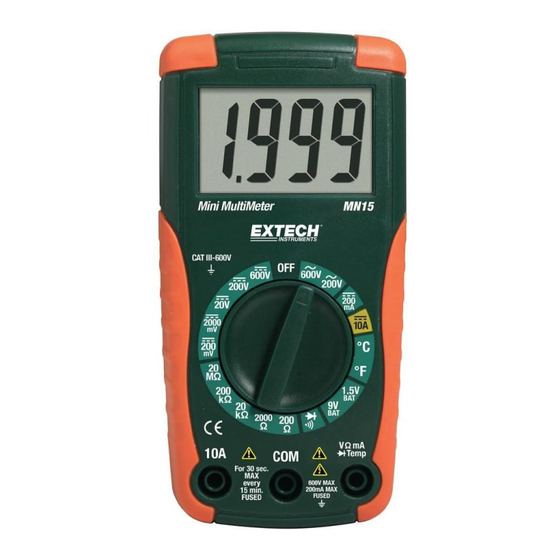
- Page 1 User's Guide Mini Digital Multimeter Model MN15...
- Page 2 Introduction Congratulations on your purchase of the Extech MN15 MultiMeter. The MN15 offers AC/DC Voltage, AC/DC Current, Resistance, Diode, and Continuity testing plus Type K thermocouple temperature measurements. Proper use and care of this meter will provide many years of reliable service.
-
Page 3: Controls And Jacks
Input Protection Limits Function Maximum Input VDC or VAC 600VAC and VDC VDC or VAC 200mV range 200Vrms mA AC/DC 200mA 250V fast acting fuse A AC/DC 10A 250V fast acting fuse (for 30 seconds max. every 15 minutes.) Resistance, Continuity 250Vrms for 15 sec. -
Page 4: Ac Voltage Measurements
Operating Instructions WARNING: Risk of electrocution. High-voltage circuits, both AC and DC, are very dangerous and should be measured with great care. NOTE: On some low AC and DC voltage ranges, with the test leads not connected to a device, the display may show a random, changing reading. This is normal and is caused by the high-input sensitivity. -
Page 5: Dc Current Measurements
DC CURRENT MEASUREMENTS CAUTION: Do not make current measurements at 10 Amps for longer than 30 seconds. Exceeding 30 seconds may cause damage to the meter and/or the test leads. Insert the black test lead banana plug into the negative COM jack. For current measurements up to 200mA, set the function switch to the 200mA position and insert the red test lead banana plug into the mA jack. -
Page 6: Resistance Measurements
RESISTANCE MEASUREMENTS WARNING: To avoid electric shock, disconnect power to the unit under test and discharge all capacitors before taking any resistance measurements. Set the function switch to the highest Ω position. Insert the black test lead banana plug into the negative COM jack. Insert the red test lead banana plug into the positive Ω... -
Page 7: Battery Voltage Test
BATTERY VOLTAGE TEST CAUTION: Do not measure batteries while they are installed in the devices they are powering. The batteries must be removed from installations before tests can be made. Set the function switch to the 1.5V or 9V BAT switch position. Use the 1.5V position for ‘AAA’, ‘AA’, ‘C’, ‘D’, and other 1.5V batteries. -
Page 8: Maintenance
Maintenance WARNING: To avoid electric shock, disconnect the test leads from any source of voltage before removing the back cover or the battery or fuse covers. WARNING: To avoid electric shock, do not operate your meter until the battery and fuse covers are in place and fastened securely. -
Page 9: Fuse Replacement
FUSE REPLACEMENT Disconnect the test leads from the meter. Remove the 2 Phillips head screws located on the back of the instrument and remove the battery cover. Gently remove the fuse(s) and install the new fuse(s) into the holder(s). Always use fuses of the proper size and value (200mA/660V ceramic fast blow for the mA / µA ranges, 10A/250V ceramic fast blow for the A range). -
Page 10: General Specifications
Equipment of OVERVOLTAGE CATEGORY IV is for use at the origin of the installation. Note – Examples include electricity meters and primary over-current protection equipment ©Copyright © 2008 Extech Instruments Corporation (a Flir company) All rights reserved including the right of reproduction in whole or in part in any form.
Need help?
Do you have a question about the Extech Instruments MN15 and is the answer not in the manual?
Questions and answers